

3
86
E
N
G
IN
E ASS
E
M
B
LY AN
D CO
NTRO
LS
2
8
9
6
5
7
4
1
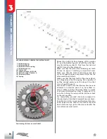
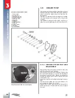
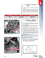
6Nm
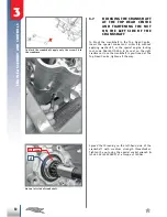
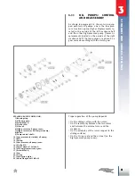
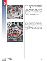
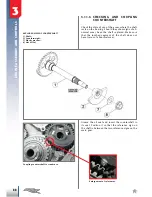
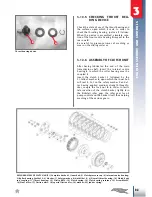
3.11.4 CHECKING AND ASSEMBLY OF
OIL PUMPS CONTROL GEARS
The oil pumps are controlled by a gear cascade dri
-
ven by the clutch gear.
The gearwheels, being made of plastic, must not
have chips, grains or signs of abnormal wear.
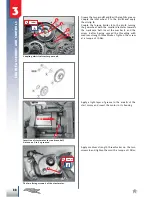
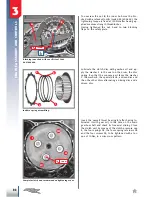
If pump control idler wheel support pin
1
should
be dismounted, reconnect it to the crankcase. The
pin is fastened to the crankcase with screw
2
(after
application of medium strength threadlockers) and
locked with 6Nm torque.
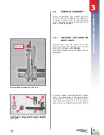
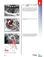
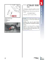
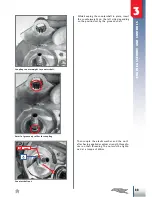
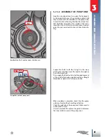
Couple the thrust washer
4
to the pin
2
and lubrica
-
te it with gear oil.
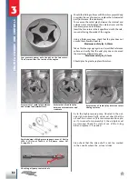
Couple the pump control idler wheel
5
to the pin so
that the most protruding segment faces the casing.
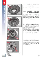
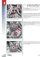
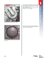
Then insert the thrust washers
6
and circlips to keep
the wheels from coming off the pins.
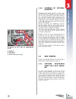
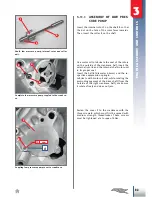
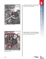
Insert the roller
7
to the end of the pump control
shaft.
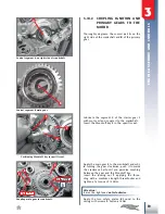
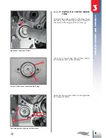
Couple the oil pump control wheel
8
to the end of
the shaft so that the groove on the gear inserts into
the roller. Then apply the benzing ring
9
, so that the
gear does not slip off.
Oil pumps control gearwheels support pins.
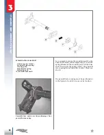
Coupling pump control gearwheels to crankcase.
Coupling pump control wheel.