FlowStar2 LB 514
2. HPLC Monitor
25
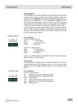
Analog Output
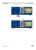
Analog signals which are proportional to the radioactivity are output to the
analog output pins for the integrator or an external evaluation system. The
scale is set on the
Methods
menu (Methods parameters page 2). The in-
formation in the dialog refers to 1 Volt: e.g.
Value at 1 V [Unit / V]:
1000,
then 1000 cpm correspond to 1 Volt at the output. The output signal goes
linear to about 2.5V (i.e. 300%), so that
– in our example – count rates up
to 2500 cpm will be transferred. Values above 2500 cpm will be cut off.
An A/D converter may be connected to this output to convert the radio sig-
nal into a HPLC system compatible information. The wiring is made de-
pending on the available hardware using the cable supplied (loose ends)
or HPLC system specific cables.
Pin assignment
for the 1
st
counting channel
Out1+
"+" output signal
GND
"-" or Analog ground
Shield
shielding pin
for the 2
nd
counting channel
Out2+
"+" output signal
GND
"-" or analog ground
Shield
shielding pin
If only one counting channel is activated, the output signals are always
applied to the 1
st
counting channel.
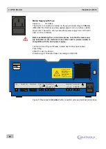
Analog Input
External detectors, for example, UV or fluorescence detectors, can be con-
nected to these inputs. The input range is at max. +/-5V. The wiring is made
depending on the available hardware using the cable supplied (loose
ends).
Pin assignment
for the 1
st
analog channel
In1+
positive input channel 1 (differential signal)
In1-
negative input channel 1(differential signal)
GND
Analog ground
In2+
positive input channel 2 (differential signal)
In2-
negative input channel 2(differential signal)
GND
Analog ground
Analog Output
O
u
t1
+
G
N
D
S
h
ie
ld
O
u
t2
+
G
N
D
S
h
ie
ld
Analog Input
In
1
+
In
1
-
G
N
D
In
2
+
In
2
-
G
N
D


