background image

A: R82GB0GA.PMD
B: R82DE0GA.PMD

E: 080403 / T.Wenger

G: 020403  / TCS

Section 6
Page 2

Operation

0

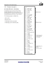
Press START + Totmann button on the MCD

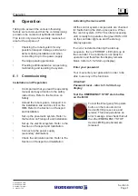
After checking the EMERGENCY
STOP line and activating the
EMERGENCY STOP slam button
press the green ”START” button and
the ”TOTMANN” button on the MCD

simultaneously.

The main contactor then connects the power
supply to the ACOPOS servo booster. The
power is now ON!  If the power supply is not
connected this generates an error message.

The ACOPOS servo booster is now ready for
operation.  The motor holding brakes remain
activated.  The three servo axes are not
controlled. (Axis change-over)

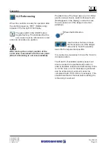
Confirm error

Any occurring errors, as well as potential errors,
must be remedied and confirmed before any
further movements can be carried out.

If an error occurs, this is indicated to the
operator by the red LED in the "ERROR" button.

Press the "ERROR" button to switch to the
"ERROR" page in the display.

After remedying the error, press the F1 function
button to confirm the error message or allow it
to disappear automatically. (refer to 5.5.8 Error
messages)

Содержание UNILOG B2

Страница 1: ...ng Manual UNIROB R8 UNILOG B2 Version R82GBV00 04 03 Read before using the robot and keep it near the robot for reference purposes Robot Type R8 B2 6 10 20 Controller type UNILOG B2 Robot No 26358 Mod...

Страница 2: ...einerzhagen Tel 49 2354 72 0 Fax 49 2354 72 234 Battenfeld Kunststoffmaschinen Ges m b H Wr Neust dter Stra e 81 A 2542 Kottingbrunn Tel 43 2252 404 0 Fax 43 2252 404 261 www battenfeld com DINENISO90...

Страница 3: ...ge 1 Chapter 1 General information Chapter 2 Safety Chapter 3 Technical Data Chapter 4 Transport Installation Chapter 5 Structure and function Chapter 6 Comissioning Chapter 7 Maintenance Chapter 8 Sp...

Страница 4: ...A PB2GBI1A P65 B PB2DEI1A P65 E 180202 Ruder G 190202 G Krajnik Section IN1 Page 2 Index...

Страница 5: ...s 3 1 2 Handling loads 3 1 3 Mechanical interface 3 1 4 Delivery side selection 3 2 Robot axles 3 2 1 Linear axles 3 2 2 Auxiliary axes 3 3 Performance data Mechanical interfaces Technical features 3...

Страница 6: ...ng 4 1 3 Securing devices 4 1 4 Crane transportation 4 1 5 Transport weight 4 1 6 Injection moulding machine assembly 4 1 7 Installation layout 4 1 8 External stand 4 1 9 Removing protective coatings...

Страница 7: ...s 5 5 2 Start up display 5 5 3 Status pages 5 5 4 Teach Edit Save Load Delete Print programs 5 5 5 Creating token programs 5 5 5 1 Token commands Gripper GRP Robot ROB Injection Moulding Device IMD 5...

Страница 8: ...7 4 1 Compressed air servicing unit 7 4 2 Pneumatic connections 7 4 3 Pneumatic C axes 7 4 3 1 Settings C axis tilting 7 4 4 Pneumatic B axes 7 4 4 1 Settings B axis swivel 7 4 5 Pneumatic installatio...

Страница 9: ...notes for initial operation A factory password is required for robot operation It enables the user to switch to Password level 1 PASSWORD 2002 Further details of the various password levels can be fou...

Страница 10: ......

Страница 11: ...ty for any damage or stoppages which are due to failure to read the manual We offer operator training courses in our company In house courses can also be arranged Contact our Training Department for f...

Страница 12: ...h may result in physical and fatal injuries Areas labelled Hot surface indicate there is a risk of burning Operators and service engineers must wear suitable protective clothing refer to DIN EN 407 Da...

Страница 13: ...is intended for assembly operating and monitoring staff It contains regulations and diagrams which may not be copied distributed or used for competitive purposes in part or whole without prior authori...

Страница 14: ...A R82GB0AA PDM B R82DE0AA PDM E 080403 T Wenger G 020403 TCS Section 1 Page 4 General...

Страница 15: ...____________________________________________________________________________ 3 The robot specified under Item 1 was acquired by our company Upon receipt of the robot we were supplied with ____________...

Страница 16: ...A R82GB0AA PDM B R82DE0AA PDM E 080403 T Wenger G 020403 TCS Section 1 Page 6 General...

Страница 17: ...ons or changes which may affect the operating safety of the system Intended use of the system shall include adherence to the assembly dismantling start up operation and maintenance procedures specifie...

Страница 18: ...not stand or work under suspended loads Loads may only be attached secured and transported by experienced authorised specialists The robot system may only be transported using the eyebolts and elemen...

Страница 19: ...he IMM and the robot system have been shut down and secured When operating the ejector mechanisms or the core pullers with the safety door open it is necessary to ensure that there are no crushing or...

Страница 20: ...caught in moving parts Responsibility for assembly disassembly commissioning operation and maintenance activities must be clearly defined and adhered to in order to avoid any potential misunderstandi...

Страница 21: ...Operators must always follow the shutting down procedures specified in the operating manual when carrying out any work on the IMM and the robot system The operator must immediately report any changes...

Страница 22: ...ssembly disassembly conversion and maintenance work may therefore only be carried out by electricians according to DIN VDE 0105 or DIN EN 60204 1 The electrical system may only be connected to a power...

Страница 23: ...a portal robot whose main axes consist of two horizontally aligned unsupported linear axes X Y and a vertically aligned linear axis Y It has a maximum of two B C auxiliary axes The linear axes main a...

Страница 24: ...ric motors X main horizontal linear axis parallel to the first axis of the reference co ordinate system IMM longitudinal direction Z main horizontal linear axis parallel to the second axis of the refe...

Страница 25: ...ntre of the gripper mounting 3 3 3 Maximum speeds of main and linear axes Position detection ACOPOS servo assisted B R drive mechanism refer to 5 3 1 Electric motors 3 3 4 Maximum speeds of rotating a...

Страница 26: ...the system 3 4 2 Creating a vacuum The vacuum which is required to operate the gripper is created using a vacuum injector Venturi principle A blow out function is used to place the components in the c...

Страница 27: ...s for main linear axes The servo controlled axle drives are fitted with integrated motor brakes which are activated at the end position Standard high quality bearings permit speeds ranging from approx...

Страница 28: ...amped to the immersion pipe and a pinion attached to the gear shaft 3 8 Mechanical interface 3 8 1 Gripper interface The gripper flange measures 80 x 80 mm 3 15 x 3 15 inches with a centred M6 40 x 20...

Страница 29: ...orward movement has been reached It must not be possible to accidentally adjust the opening to a narrower setting than the minimum required tool width The signal must be indicated while the tool is op...

Страница 30: ...e closing sequence has been completed The Start closing signal is then cancelled 3 10 3 Handling device signals 17 32 Start Tool close sequence by HD Activate Tool close The contact is closed when the...

Страница 31: ...de switch Opened contact signals to IMM Operation with HD Position 1 Closed contact signals to IMM Operation without HD Position 0 21 32 Ejector retracted from HD The closing contact returns the tool...

Страница 32: ...A R82GB0CA PDM B R82DE0CA PDM E 080403 T Wenger G 020403 TCS Section 3 Page 10 Specifications...

Страница 33: ...rom improper assembly 4 1 1 Storage All robots are adequately packaged in order to prevent any damage occurring in transit The robot must be put into operation immediately after it has been delivered...

Страница 34: ...any of the robot components Safety harnesses must be worn when working at heights If the robot is mounted on the injection moulding machine it is important to ensure that the machine is aligned to wi...

Страница 35: ...ttention to the manufacturer s instructions It is also important to observe local regulations relating to the disposal of such liquids and impregnated cleaning cloths 4 2 Connecting to the power suppl...

Страница 36: ...ctivating the electrical systems for the first time It is important to adhere to each of these points in order to ensure that the machine runs properly 4 3 1 Connecting to the power supply Connect up...

Страница 37: ...control cabinet to start the control system The motors are initially interrupted by the main fuse 40 K1 4 3 6 EMERGENCY STOP test To test the EMERGENCY STOP hardware and software on the manual control...

Страница 38: ...A R82GB0DA PMD B R82DE0DA PMD E 080403 T Wenger G 020403 TCS Section 4 Page 6 Transport Installation...

Страница 39: ...B R82DE0EA PMD E 170403 T Wenger G 020403 TCS Section 5 Page 1 1 2 4 3 5 Assembly and Operation 5 1 Modules 1 Pneumatic system refer to 5 2 2 Electric motors refer to 5 3 1 3 Terminal box 1 refer to...

Страница 40: ...et reset the clamping circuits Principle Electrical indirectly activated 5 2 bistable directional valve The valve remains in position after it has been adjusted until it is reset by a counter signal S...

Страница 41: ...pneumatic elements from premature wear Attention The robot system pneumatics may only be operated using oil free air 5 3 Electrical systems 5 3 1 Electric motors General The three linear axes on the 3...

Страница 42: ...e or floppy disc DSUB9 3 Main switch 4 Conveyor belt cable gland 5 Peripheral cable gland 6 Power supply 3x400V cable gland 7 HAN_E plug power supply connection 3x400V ACOPOS servo booster 8 HAN24 ope...

Страница 43: ...pply After switching off the devices the intermediate circuit requires a discharge time of at least 5 minutes Use a suitable measuring device to check that the current intermediate circuit voltage is...

Страница 44: ...of the tolerance range Motor overheated Servo booster overheated Braking resistance overheated CAN or powerlink network fault LED indicators Red LED Power is switched off Green LED POWER ON and system...

Страница 45: ...type Description Programmed configuration Incorrect table entry bus coupler Table comparison Terminal n incorrect Description Terminal bus command fault Description Terminal bus data error Breakage be...

Страница 46: ...ted terminal at n KL1104 input terminals Signal LED 1 Signal LED 3 A B C D E2 E3 E4 1 2 3 4 5 6 7 8 Power contacts Top view E1 R8B2_019 PDF KL2134 output terminals Signal LED 2 Signal LED 1 Signal LED...

Страница 47: ...can be saved to a floppy disc via an RS232 interface or printed out R8B2_021 JPG 5 4 1 Manual Control Device MCD The MCD consists of LCD approx 2 76 with 8 x 21 character lines Green START button and...

Страница 48: ...pansion units Two CAN node number switches eliminate the need for offset adjustments The actual node number always corresponds to the switch position 5 4 3 CP476 status display R8B2_021 JPG LED Colour...

Страница 49: ...h position for Node number 1 RIGHT 0 LEFT 1 R8B2_029 JPG Positions 00 FD FE and FF are reserved for special software programming functions not required for standard operation 5 4 5 Digital Input Outpu...

Страница 50: ...digital inputs 24 V DC input voltage 1 ms input delay 8 digital outputs 24 V DC switching voltage Max continuous current 0 5 A per output Short circuit and overload proof R8B2_031 JPG R8B2_032 JPG DO7...

Страница 51: ...Handbook UNIROB R8 UNILOG B2 Version R82GBV00 04 03 Read before using the controller and keep it near the controller for reference purposes...

Страница 52: ...einerzhagen Tel 49 2354 72 0 Fax 49 2354 72 234 Battenfeld Kunststoffmaschinen Ges m b H Wr Neust dter Stra e 81 A 2542 Kottingbrunn Tel 43 2252 404 0 Fax 43 2252 404 261 www battenfeld com DINENISO90...

Страница 53: ...numerical value Press STOP to interrupt the movement The red LED in the STOP button lights up when the power is deactivated or when the robot has been stopped in Automatic mode 2 PROG button Press the...

Страница 54: ...tton twice in User level 2 to switch to the Service page In Program mode it switches to the Axis selection page The orange LED belonging to this button lights up when one of these pages is selected 8...

Страница 55: ...this button lights up when the numerical pad is activated 14 ESC Press the ESC button to switch to the Start up display or in Programming mode to move back one level to the program 15 C button The C C...

Страница 56: ...t 5 5 2 Start up display These details appear in the MCD display when the controller is activated Top line 1 err flashes if an error has been detected 2 The current operating mode is shown here i e MA...

Страница 57: ...nitor the current program Use the arrow buttons to move the selected axes The Snail and Hare buttons are used to adjust the override The current axis positions Actual values are shown on the Axis stat...

Страница 58: ...acuum circuit statuses in Manual and Automatic mode The clamping circuits can be set and reset in Manual mode IMM status page IMM button Press IMM button R8B2_GB057 JPG R8B2_GB058 JPG This display sho...

Страница 59: ...Press the Periphery button Here all the Periphery signals digital inputs and outputs are displayed in Manual and Automatic mode The digital outputs can be set and reset in Manual mode R8B2_GB145 JPG C...

Страница 60: ...S button Press the PCS button The status of the current Palletising programmes are shown here in Manual and Automatic mode Counter in X Y Z direction Select F4 to reset the counter of any selected pal...

Страница 61: ...ch Edit Save Load Delete Print programs General Display is possible in Manual mode MAN and from Password level 1 upwards Continue by pressing F4 according to the cursor position EDIT TEACH program The...

Страница 62: ...tion and Control System R8B2_GB067 JPG R8B2_GB068 JPG R8B2_GB067 JPG R8B2_GB069 JPG Save Press the PROG button Press the buttons to move the cursor to Save program Press F4 to continue Load Press the...

Страница 63: ...Delete program Press F4 to continue In the start display use the buttons to move the cursor to the Delete project program Press F4 to continue New project Select Yes to delete the lines in the current...

Страница 64: ...m display to create an Automatic program see 5 5 4 Example NC axes command Use the F4 button Teach Edit to enter the corresponding command in the previously selected line of the token program Attentio...

Страница 65: ...R8B2_GB076 JPG R8B2_GB077 JPG R8B2_GB078 JPG Press the ROB button Select the axis to be edited e g X axis Move Absolute 300 Attention In TEACH programming mode the system will automatically move to th...

Страница 66: ...chine IMM Gripper GRP V1 BLOUT 01 00 G2 OPEN Blow out vacuum gripper 01 00 s Open gripper V1P BLOUT 01 00 G2P OPEN Blow out vacuum gripper parallel 01 00 s Open parallel gripper V1 VACUUM G2 CLOSE Att...

Страница 67: ...00 100 00 Absolute axis position with parallel value Position 1 End point Position 2 Command in next command line xStp 0100 00 X axis stack stop at 100 00 The selected axis moves to the target positio...

Страница 68: ...e signal is 0 or 1 the system then jumps to a label The IMM signals to the robot system that the ejectors are fully extended by setting the signal to logic 1 This signal is frequently used so that the...

Страница 69: ...indicate to the robot system that the core pullers are ready to remove the casting This signal is used to prevent the casting from being removed before it has been fully released by the core pullers...

Страница 70: ...machine that the mould can be opened further by setting the Enable TL open signal to logic 1 The machine then pulls the long core out of the barrel shaped vessel and activates the Tool open signal whe...

Страница 71: ...back Enable Ejector back Ej back Ejector is back Ej forw Enable Ejector forward Autom IMM in Automatic Cp rem Enable Core puller to Removal Pos Cp rem Core puller in Removal Pos Cp forw Enable Core pu...

Страница 72: ...to main program Activated automatically at end of subprogram Set 5 Uv 10 Sets user variable CLEAR 6 Uv Deletes user variable INC 8 Uv Defines an increment The user variable value is increased by 1 DEC...

Страница 73: ...row keys to adjust the individual objects If commands Use the cursor buttons to select If R8B2_GB64 JPG Type 1 Description Value1 Description Uservar User variable 1 10 User variable number Enter actu...

Страница 74: ...standard peripheral interface and a conveyor interface The peripheral interface enables you to control one of your application peripheries with 4 digital inputs outputs from the token program special...

Страница 75: ...digital input is logic 0 or 1 and then jumps to the label No time need be specified When the conditions have been fulfilled the system jumps to the label D12 if0 L6 D12 if1 L6 When the digital input i...

Страница 76: ...8B2_128 JPG R8B2_GB064 JPG R8B2_GB086 JPG Conveyor The conveyor interface enables you to integrate a conveyor into the system Press the PROG button Press the Periphery button From the Wait objects poi...

Страница 77: ...F both signals must be logic 1 WaPos1 Signal ON WaPOS1 Signal OFF The system waits for the Position space free input signal OFF indicates that the position is free ON indicates that it is occupied IfC...

Страница 78: ...rate basic positioning and removal tasks into the token program Example of the palletising input 1 Palletising tasks First position Removal tasks Final position 2 Palletising tasks Final position Pall...

Страница 79: ...DIT function If the program already exists the old values are displayed on the right Use the arrow buttons to select the Palletising program No The type of entry can be selected here First position Sp...

Страница 80: ...PalProg 1 START This command starts the selected palletising program Definition The system moves to the next position following the specified movement sequence PalProg 1 RESET All counters are zeroed...

Страница 81: ...029 y 800 0 030 V1 BLOUT 0 6 Positioning cycle 031 y 10 0 for good casting 032 Con ON 2 0s on conveyor 033 x 10 0 034 z P 75 0 1400 0 035 C 036 PStop 037 Goto 1 038 Label 2 039 z P 1000 0 75 0 040 C 0...

Страница 82: ...28 V1 BLOUT 0 6 029 y 10 0 030 x 10 0 Positioning cycle 031 z P 75 0 1400 0 for good casting 032 C on conveyor 033 PStop 034 Pal 1 Pal full L2 035 Goto 1 036 Label 2 037 Callsub 1 038 Goto 1 039 Label...

Страница 83: ...n the PalStat page after positioning Notes All the PalStat page data for this palletising program are displayed together The PalStat page only shows the each current line In palletising pattern XYZ Z...

Страница 84: ...iagram Lock area 1 mould area is only treated as a lock area provided the mould is not fully open This lock area is deactivated by the Start handling device procedure or Tool at intermediate stop IMM...

Страница 85: ...EACH enter mode is selected the system will automatically move to the selected value when START is pressed Use the arrow buttons with the cursor positioned accordingly to activate deactivate the Enabl...

Страница 86: ...GB104 JPG R8B2_GB105 JPG R8B2_GB102 JPG Specify the area to be protected the gripper and the auxiliary axes The old values are shown on the right Enter the end coordinates for the selected lock area i...

Страница 87: ...s stopped ACOPOS servo booster indicates an error To remedy 1 Reconnect the power supply 2 Activate movement in the opposite direction This error may indicate that the software limit positions have be...

Страница 88: ...the robot in the mould area To remedy Switch to Manual control and move the axes out of the mould area Confirm error 52 53 Casting Mon 1 One of the casting monitoring devices was activated and the req...

Страница 89: ...rrent servo axis stops moving Enable signals to IMM disappear Movement of all pneumatic axes and gripper functions is blocked To remedy Check compressed air Press the START button on the MCD System co...

Страница 90: ...ot activated or power supply not connected To remedy Power ON Confirm error 126 Controller error Effect Controller indicates an error Select F4 to view more details on the PCS ERROR page refer to ACOP...

Страница 91: ...protruding from the battery compartment Mount the cover Make sure that the screwdriver recess is facing upwards 1 First insert the top end of the cover into the recess of the battery compartment 2 Pr...

Страница 92: ...A R82GB0FA PMD B R82DE0FA P65 E 080403 T Wei G 020304 TCS Section 5 5 Page 40 Operation and Control System...

Страница 93: ...rt and Installation Set up the electrical system Refer to the Section on Transport and Installation Connect up the power supply secondary distribution Check the lubrication points Refer to the Section...

Страница 94: ...s generates an error message The ACOPOS servo booster is now ready for operation The motor holding brakes remain activated The three servo axes are not controlled Axis change over Confirm error Any oc...

Страница 95: ...axes are in a critical position visual check switch to Manual mode MAN appears in the display in order to move the axis axes out of the danger zone tool periphery Press the MAN button Use the arrow b...

Страница 96: ...the horizontal axes X Z move towards their reference points When all three linear axes have reached their reference positions HOME appears at the top right of the display and the controller automatica...

Страница 97: ...Status pages Axis status display The override function is adjusted in 5 increments Minimum value 5 Maximum value 100 using the two buttons snail hare to the left and right of the arrow buttons Overri...

Страница 98: ...ssed again The green LED in the START button then begins flashing Press the TOTMANN button and the START button to start the program sequence The token program sequence is carried out line by line i e...

Страница 99: ...mode refer to Section 5 5 3 Status pages Press the F4 function button continue to read off the current program status Press the START button to execute the command in the marked program line Exiting...

Страница 100: ...the program or until it is interrupted by the user Status displays The status displays are used in the same way as in Single step mode refer to 6 4 Automatic mode speeds In Automatic mode the linear a...

Страница 101: ...ic program uses jumps to different labels it is necessary to insert the Pstop command line The Automatic program runs until the last program line and then stops End of cycle The control system is stil...

Страница 102: ...ion is reached The control system is still in Automatic mode Press the TOTMANN button and the START button to restart the program sequence Exiting Automatic mode Press the MAN button to switch to Manu...

Страница 103: ...work as well as any detected defects and repairs which are carried out The various operating conditions make it impossible specify how often it is necessary to check for wear and carry out servicing...

Страница 104: ...port Storage and Waste disposal 7 2 2 Electrical components Pay attention to local laws and regulations when disposing of electrical and electronic components 7 3 Electrical systems It is essential th...

Страница 105: ...ately 7 3 4 Control cabinet The doors on the control cabinet must always remain closed whilst the machine is in operation Make sure that the control cabinet is kept clean Carry out visual checks on el...

Страница 106: ...tional 7 4 2 Pneumatic connections Check all pneumatic connections are securely tightened e g downstream valve block 7 4 3 Pneumatic C axis The swivel axis is a compact twin blade part turn actuator T...

Страница 107: ...ce free ball bearings on both sides inside the housing The part turn actuator rotates at a maximum angle of 100 The smooth shafts are connected to the swivel fork by a clamping hub The required angle...

Страница 108: ...The hose ends must be cut off using a special cutter Check the integrated compressed air connectors screw unions quick release screw fittings and instant plug in connectors for leaks every month and...

Страница 109: ...laced together Pay attention to the markings on the joints It is necessary to break away the covers in order to access the mounting bolts on the guiderails Any broken or damaged covers must be replace...

Страница 110: ...ion involves using a total of 3 separate amounts of grease as specified in the table 1 Apply the first amount of grease to the guide unit as specified in the table 2 Move the guide unit back and forth...

Страница 111: ...PMD E 080403 T Wenger G 020403 TCS Section 7 Page 9 R8B2_096 JPG X axis 3 lubrication points R8B2_097 JPG R8B2_126 JPG Y axis 4 lubrication points R8B2_152 JPG Z axis 4 lubrication points R8B2_153 JPG...

Страница 112: ...is Z axis The toothed belt runs between the fixed plate above the deflection pulley drive roller and clamping plate To change the belt tension it is necessary to slacken off the 4 clamping bolts Pos 1...

Страница 113: ...ews Pos 2 in the cover plate on the axis support Then retighten the clamping bolts 7 6 1 3 Toothed belt replacement If a damaged toothed belt has to be replaced it is important that the new belt is re...

Страница 114: ...pecifications can be found on the housing 7 7 Power guide chains Power supply chains partly unsupported or in channels are used to provide moveable loads with safe maintenance free supplies of electri...

Страница 115: ...the total operating hours ED 40 If any major deviations occur appropriate changes must be made Non operation based testing and maintenance procedures must be specified as follows d daily w weekly m m...

Страница 116: ...y if defective Door closed during operation Always Clean m Visual check w Tighten terminals 2500h Battery 7 3 5 Replace when indicated Condensate status check empty w Eingangsdruck pr fen w Clean cond...

Страница 117: ...e w Check for tightness w Cover plate 7 5 Replace Repairs and Servicing Check for tightness m Check for damage m Tension 1000h Replace Repairs Drive 7 6 2 Check for leaks Repairs Power chains 7 7 Chec...

Страница 118: ...A R82GB0HA PMD B R82DE0HA PMD E 080403 T Wenger G 020403 TCS Section 7 Page 16 Maintenance...

Страница 119: ...robot system There is an assembly drawing for each module Each spare part can be found under a separate Item number In order to avoid confusion it is necessary to specify the Machine No on each spare...

Страница 120: ...A R82GB0IA PMD B R82DE0IA PMD E 080403 T Wenger G 020403 TCS Section 8 Page 2 Spare parts Diagrams...

Страница 121: ...OC P65 E 180202 Ruder G 180202 G Krajnik Chapter 9 Page 1 9 0 Customer Service 9 1 General The Customer service chapter contains all contact addresses of all customer service partners and agencies of...

Страница 122: ...Canada Tel 001 905 6709384 Fax 001 905 7958226 e Mail batt netrover com Chile BBL PACK S A Av Pedro de Valdivin No 3317 Nu oa Santiage Chile Tel 0056 2 209 2880 Fax 0056 2 209 2869 e Mail bbl entelch...

Страница 123: ...Marketing Est P O Box 1505 Amman Jordan Tel 00962 6 611906 Fax 00962 6 611907 Yugoslavia Fokuma Planungs u Vertriebsges m b H Further Stra e 27 A 2564 Wei enbach Tel 0043 2674 87427 0043 2674 87413 F...

Страница 124: ...enfeld pcnet ro Russia Vadim Zviagintsev 1 Novokuznetzkij Per 5 7 KW 37 113184 Moskau Russische F deration Tel 007 095 9538077 Tel 007 095 3051466 Fax 007 095 2306261 Sweden VSV Battenfeld Sverige AB...

Страница 125: ...3700010 Fax 0036 1 3700020 e Mail thege netvision hu Uruguay GMO Gabelsberger Cia S A siehe unter Argentinien U S A VUS Battenfeld of America Inc James P Murphy Ind Highway West Warwick Industrial Par...

Страница 126: ...49 0 2354 72 139 e Mail Hinz m bmf battenfeld com Technical Customer Service Tel 49 0 2354 72 160 Fax 49 0 2354 72 169 e Mail Salmen j bmf battenfeld com Spare Parts and Technical Customer Service Te...

Отзывы: