Operation
A: R82GB0GA.PMD
B: R82DE0GA.PMD
E: 080403 / T.Wenger
G: 020403 / TCS
Section 6
Page 1
0
6
Operation
Taking into account the various influencing
factors we recommend that the commissioning
procedure be carried out by Battenfeld staff.
This is not only done for warranty reasons but
also for the purpose of:
•
Checking the robot system for any
possible transport damage and also for
defects during installation and when
connecting it up to the power supply.
•
Training operating personnel.
•
Providing additional advice on operating,
maintaining and repairing the system.
6.1
Commissioning
Installation and Preparation
•
It is important that you read the operating
manual and pay attention to the safety
instructions. Refer to the Section on
Safety.
•
Unload the robot system, transport it to
the installation site and mount it on the
IMM. Refer to the Section on Transport
and Installation.
•
Set up the pneumatic system. Refer to
the Section on Transport and Installation.
•
Set up the electrical system. Refer to the
Section on Transport and Installation.
•
Connect up the power supply
(secondary distribution).
•
Check the lubrication points. Refer to the
Section on Transport and Installation
Activating the main switch
All the control system components are checked
for faults during the start-up sequence. When
the control system (CP 476 central processing
unit) is ready for operation, the green RUN LED
on the controller lights up and the start-up
display appears.
If an error is detected during the start-up
sequence, the red ”ERROR” LED lights up at
the controller. The controller is not ready for
operation and therefore the display remains
blank. (refer to 5.5.2 Start-up display)
Enter your password
Your must enter your password in order to be
able to use any of the functions.
Attention!
Password level - refer to 5.5.2 Start-up
display
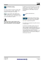
Test the EMERGENCY STOP slam button
on the MCD
To test the Emergency Stop slam
button on the manual control
device (MCD) press once and
release. This also generates an
error message. Also check that all
the other EMERGENCY STOP
devices (IMM, peripherals) are
released.
Содержание UNILOG B2
Страница 4: ...A PB2GBI1A P65 B PB2DEI1A P65 E 180202 Ruder G 190202 G Krajnik Section IN1 Page 2 Index...
Страница 10: ......
Страница 14: ...A R82GB0AA PDM B R82DE0AA PDM E 080403 T Wenger G 020403 TCS Section 1 Page 4 General...
Страница 16: ...A R82GB0AA PDM B R82DE0AA PDM E 080403 T Wenger G 020403 TCS Section 1 Page 6 General...
Страница 32: ...A R82GB0CA PDM B R82DE0CA PDM E 080403 T Wenger G 020403 TCS Section 3 Page 10 Specifications...
Страница 38: ...A R82GB0DA PMD B R82DE0DA PMD E 080403 T Wenger G 020403 TCS Section 4 Page 6 Transport Installation...
Страница 92: ...A R82GB0FA PMD B R82DE0FA P65 E 080403 T Wei G 020304 TCS Section 5 5 Page 40 Operation and Control System...
Страница 118: ...A R82GB0HA PMD B R82DE0HA PMD E 080403 T Wenger G 020403 TCS Section 7 Page 16 Maintenance...
Страница 120: ...A R82GB0IA PMD B R82DE0IA PMD E 080403 T Wenger G 020403 TCS Section 8 Page 2 Spare parts Diagrams...


