


A: R82GB0FA.PMD
B: R82DE0FA.P65
E: 080403 / T. Weiß
G: 020304 / TCS
Section 5.5
Page 32
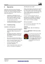
Operation and Control System
?
5.5.7 Lock areas
General
Lock areas are basically used to provide
sofeware-side backup for the mechanical
functions in the robot system and the injection
moulding device. The robot cannot enter these
areas.
Users are given a total of 5 lock areas, whereby
Lock area 1 is a fixed mould area. Lock area 2
is for the tool closing side and Lock area 3 for
the tool nozzle side.
Lock areas 4 and 5 can be used as required. A
lock area is fully defined by specifying the start
and end positions.
The start coordinates "-" of the lock area define
the minimum coordinate for each axis.
The end coordinates "+" of the lock area define
the maximum coordinate for each axis.
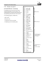
If all the "-" and "+"positions for a single lock
area of the three main axes are entered, this
produces a cube containing the lock area as
shown in the diagram.
Lock area 1 (mould area) is only treated as a
lock area provided the mould is not fully open.
This lock area is deactivated by the ”Start
handling device procedure” or ”Tool at
intermediate stop” (IMM interface) signal in order
to allow the vertical axis to be inserted between
the two mould halves.
It is important to define the mould area. This is
because the ”Enable close mould” signal is not
sent to the IMM in Set-up or Automatic mode and
the robot cannot be started automatically
(”Operating area violation” fault).
An ”Operating area violation” fault occurs when
all the axes ”violate” a lock area.
Example:
Diagram showing the lock area coordinates
Axis 1
MIN
MAX
500.00 mm
100.00 mm
Axis 2
MIN
MAX
50.00 mm
400.00 mm
Axis 3
MAX
MIN
350.00 mm
200.00 mm
locked
area
Current position
Axis 1: 475,00
Axis 2: 25,00
Axis 3: 175,00
ALL MIN coordinates
Axis 1: 500,00
Lock area start - Axis 2:
50.00 Lock area start
Axis 3: 200.00 Lock area start
ALL MAX coordinates
Axis 1: 100.00 Lock area end+
Axis 2: 400.00 Lock area end+
Axis 2: 350.00 Lock area end+
Protection AREA
Along X-axis 50,00
Along Y-axis 50,00
Along Z-axis 50,00
Содержание UNILOG B2
Страница 4: ...A PB2GBI1A P65 B PB2DEI1A P65 E 180202 Ruder G 190202 G Krajnik Section IN1 Page 2 Index...
Страница 10: ......
Страница 14: ...A R82GB0AA PDM B R82DE0AA PDM E 080403 T Wenger G 020403 TCS Section 1 Page 4 General...
Страница 16: ...A R82GB0AA PDM B R82DE0AA PDM E 080403 T Wenger G 020403 TCS Section 1 Page 6 General...
Страница 32: ...A R82GB0CA PDM B R82DE0CA PDM E 080403 T Wenger G 020403 TCS Section 3 Page 10 Specifications...
Страница 38: ...A R82GB0DA PMD B R82DE0DA PMD E 080403 T Wenger G 020403 TCS Section 4 Page 6 Transport Installation...
Страница 92: ...A R82GB0FA PMD B R82DE0FA P65 E 080403 T Wei G 020304 TCS Section 5 5 Page 40 Operation and Control System...
Страница 118: ...A R82GB0HA PMD B R82DE0HA PMD E 080403 T Wenger G 020403 TCS Section 7 Page 16 Maintenance...
Страница 120: ...A R82GB0IA PMD B R82DE0IA PMD E 080403 T Wenger G 020403 TCS Section 8 Page 2 Spare parts Diagrams...


