Manual 2100-676D
Page
37 of 45
It is important to check the software version
during installation to ensure that the latest
version has been installed. Current software
versions, change log and installation
instructions are available on the Bard website at
http://www.bardhvac.com/software-download/
NOTICE
In addition to setting up the address, the user may
also want to set the unit zone and unit of measure.
Unit addresses can only be used once per LC6000
regardless of number of zones.
To change these settings:
1) Press MENU key to access the Main Menu
screen.
2) Press UP or DOWN keys and ENTER key to
enter USER password 2000.
3) Press UP or DOWN keys to scroll to
Sys Config
;
press ENTER key.
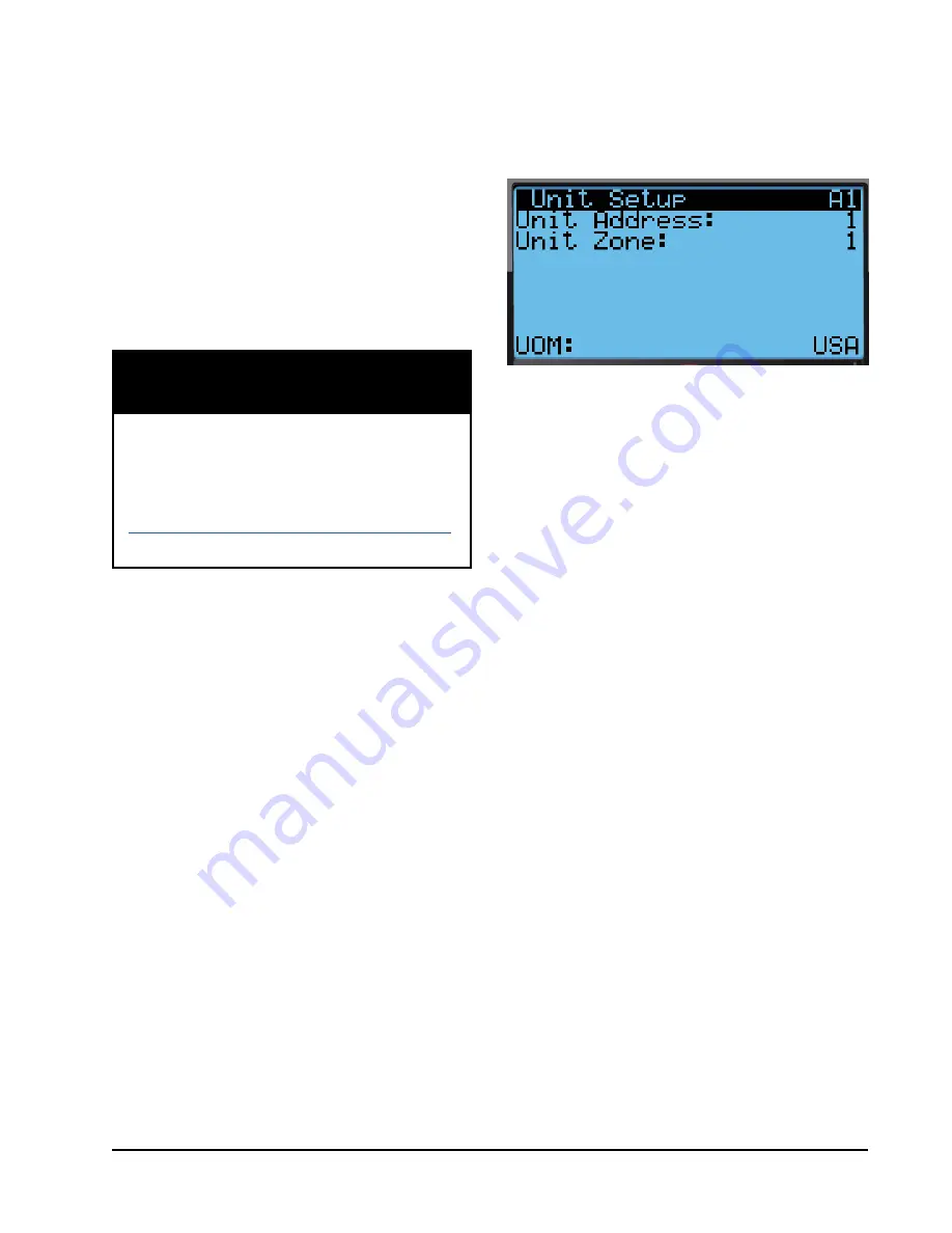
4) Press ENTER key to scroll to
Unit Zone
(see
Figure 29).
5) If desired, press UP or DOWN keys to change
value to desired zone.
6) Press ENTER scroll to
UOM
.
7) If desired, press UP or DOWN keys to change
the value from
USA
to
SI
,
NC
,
LON
,
CAN
or
UK
. Units are preconfigured for each selection.
8) Press ENTER key to save.
Basic wall unit parameter settings are now set and
the unit is ready to communicate with the LC.
2. Execute a Run Test on Each Unit
Execute a run test on each unit to verify the
equipment is functioning correctly. The run test
parameters are not adjustable.
1) Press MENU key to access the Main Menu
screen.
2) Press UP or DOWN keys and ENTER key to
enter USER password 2000.
3) Press UP or DOWN keys to scroll to
Sys Config
;
press ENTER key.
4) Press UP or DOWN keys to scroll to
Run Test
A11
screen.
TEC-EYE Status Screen
The Status screen is the default start-up screen and
also the return screen after 5 minutes of no activity.
The screen can be accessed any time by pressing the
ESCAPE key repeatedly.
The wall-mount unit address is displayed in the upper
right corner on the Status screen (see Figure 28). The
Status screen also shows the current date, time, return
air temperature, mixed air temperature, outdoor air
temperature, outdoor humidity and outdoor dew point
conditions. Blower, damper and unit status are also
displayed. See Table 6 on page 45 for wall-mount unit
status messages.
FIGURE 29
Unit Configuration
Setting Up Wall-Mount Units for
Operation
The TEC-EYE hand-held diagnostic tool is needed to set
up the wall-mount unit(s).
1. Address Each Wall-Mount Unit
Each unit must have a unique address for the
system to operate correctly with the LC controller
(
Ex: 1, 2, 3, ...14 depending on the number of
units
). The unit only needs the address to be
changed for the communication to work properly.
The wall-mount unit address is displayed in the
upper right corner on the Status screen on the
TEC-EYE display (see Figure 28).
To change the unit address:
1) Press MENU key to access the Main Menu
screen.
2) Press UP or DOWN keys and ENTER key to
enter USER password 2000.
3) Press UP or DOWN keys to scroll to
Sys Config
;
press ENTER key.
4) Press ENTER key to scroll to
Unit Address (
see
Figure 29).
5) Press UP or DOWN keys to change the address
to a value between 1 and 14.
NOTE:
Each unit must have a unique address for the
communication to work properly. Bard also
recommends physically labeling each unit for
ease in identification.
Содержание MULTI-TEC W18AAPA
Страница 2: ......
Страница 31: ......
Страница 77: ......
Страница 80: ......
Страница 84: ...Manual 2110 1442E Page 4 of 11 FUNCTIONAL COMPONENTS SEXP 177 A 1 10 11 12 5 3 4 8 7 7 2 9 6 13 ...
Страница 99: ...Manual 2100 479 Page 6 of 11 FIGURE 1 TYPICAL AIR CONDITIONING SYSTEM COOLING CYCLE MIS 369 ...
Страница 100: ...Manual 2100 479 Page 7 of 11 FIGURE 2 TYPICAL HEAT PUMP SYSTEM COOLING CYCLE MIS 368 ...
Страница 105: ......


