background image

www.baldormotion.com

Configuration 6-7

MN1943

6.3.1 Starting MMC

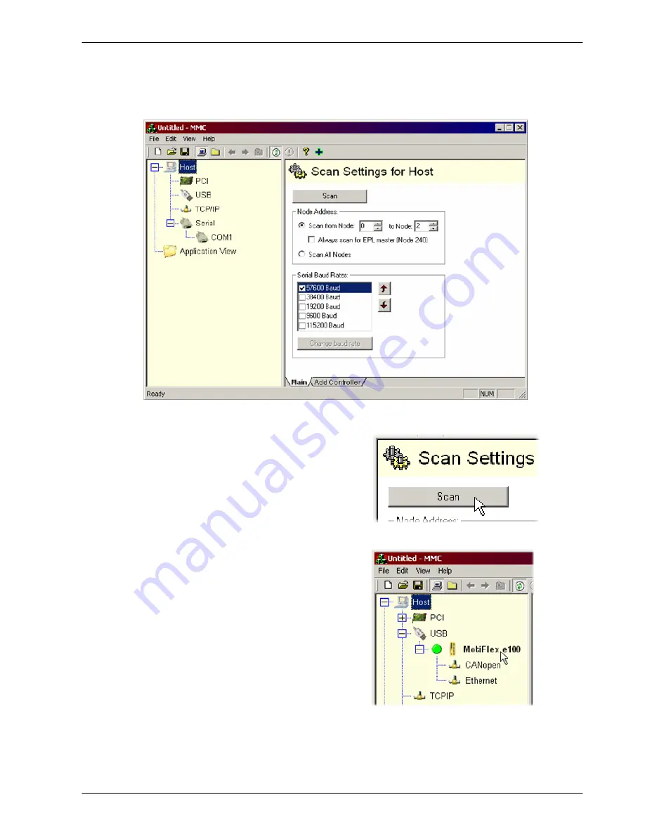
1. On the Windows

Start

menu, select Programs, Mint Machine Center, Mint Machine Center.

2. In the controller pane, ensure that Host is

selected. In the information pane, click

Scan.

3. When the search is complete, click once

on ‘MotiFlex e100’ in the controller pane to
select it, then double click to open an
instance

of

Mint

WorkBench.

The

MotiFlex

e

100 will be already connected

to the instance of Mint WorkBench, ready
to configure.

Содержание MotiFlex e100

Страница 1: ......

Страница 2: ......

Страница 3: ...A models 3 4 3 2 2 Dimensions 21 A 33 5 A models 3 5 3 2 3 Dimensions 48 A 65 A models 3 6 3 2 4 Mounting the MotiFlex e100 3 7 3 2 5 Overtemperature trips and intelligent fan control 3 10 3 3 Connector locations 3 11 3 3 1 Front panel connectors 3 11 3 3 2 Top panel connectors 3 12 3 3 3 Bottom panel connectors 3 13 3 4 AC power connections 3 14 3 4 1 Earthing grounding 3 14 3 4 2 AC input and re...

Страница 4: ...ration resistor Dynamic Brake resistor 3 36 3 8 1 Regeneration capacity 3 37 3 9 Regeneration resistor selection 3 38 3 9 1 Required information 3 38 3 9 2 Regenerative energy 3 39 3 9 3 Regenerative power and average power 3 39 3 9 4 Resistor choice 3 40 3 9 5 Resistor temperature derating 3 41 3 9 6 Resistor pulse load rating 3 42 3 9 7 Duty cycle 3 43 4 Feedback 4 1 4 1 Introduction 4 1 4 1 1 I...

Страница 5: ...er and Mint WorkBench 6 1 6 2 Starting the MotiFlex e100 6 2 6 2 1 Preliminary checks 6 2 6 2 2 Power on checks 6 2 6 2 3 Installing the USB driver 6 3 6 2 4 Configuring the TCP IP connection optional 6 4 6 3 Mint Machine Center 6 5 6 3 1 Starting MMC 6 7 6 4 Mint WorkBench 6 8 6 4 1 Help file 6 9 6 4 2 Starting Mint WorkBench 6 10 6 4 3 Commissioning Wizard 6 12 6 4 4 Using the Commissioning Wiza...

Страница 6: ...d crest factor 26 A 33 5 A models 8 13 8 2 8 Power power factor and crest factor 48 A 65 A models 8 14 8 3 Motor output 8 15 8 3 1 Motor output power X1 1 5 A 16 A models 8 15 8 3 2 Motor output power X1 21A 33 5 A models 8 15 8 3 3 Motor output power X1 48 A 65 A models 8 16 8 3 4 Motor output uprating and derating 8 17 8 3 5 Motor output rating adjustment 1 5 A model 8 17 8 3 6 Motor output rati...

Страница 7: ... interface 8 33 8 6 10 CAN interface 8 33 8 6 11 RS485 interface X6 8 34 8 7 Weights and dimensions 8 34 8 7 1 Weights and dimensions 1 5 A 16 A models 8 34 8 7 2 Weights and dimensions 21 A 33 5 A models 8 34 8 7 3 Weights and dimensions 48 A 65 A models 8 34 8 8 Environmental 8 35 Appendices A Accessories A 1 A 1 Introduction A 1 A 1 1 Busbars for DC bus sharing A 2 A 1 2 AC supply EMC filters A...

Страница 8: ... listing C 1 D CE UL D 1 D 1 Introduction D 1 D 1 1 CE marking D 1 D 1 2 Declaration of conformity D 2 D 1 3 Use of CE compliant components D 3 D 1 4 EMC wiring technique D 3 D 1 5 EMC installation suggestions D 4 D 1 6 Wiring of shielded screened cables D 5 D 2 UL file numbers D 6 ...

Страница 9: ...nauthorized persons misused abused or improperly installed and has been used in accordance with the instructions and or ratings supplied This warranty is in lieu of any other warranty or guarantee expressed or implied Baldor shall not be held responsible for any expense including installation and removal inconvenience or consequential damage including injury to any person or property caused by ite...

Страница 10: ...ntact the place of purchase for return instructions Precautions Do not touch any circuit board power device or electrical connection before you first ensure that no high voltage is present at this equipment or other equipment to which it is connected Electrical shock can cause serious or fatal injury Only qualified personnel should attempt to start up program or troubleshoot this equipment The mot...

Страница 11: ...tal heatsink on the left side of the MotiFlex e100 can become very hot during normal operation The metal part of the MotiFlex e100 case incorporates prominent edges and corners that may cause minor injury if the drive is handled without proper care and attention Take care when lifting The 48 A and 65 A models weigh 12 45 kg 27 4 lb Seek assistance if necessary When carrying do not suspend the unit...

Страница 12: ...inet that provides environmental control and protection Installation information for the drive is provided in this manual Motors and controlling devices that connect to the drive should have specifications compatible to the drive If not installed in an electrical cabinet barriers around the equipment are required Failure to meet cooling air flow requirements will result in reduced product lifetime...

Страница 13: ...H 1 optically isolated digital output to indicate error conditions H 1 motor temperature switch input H 1 general purpose 10 V analog input H USB 1 1 serial interface compatible with USB 2 0 H CANopen protocol for communication with Mint controllers and other third party CANopen devices H Ethernet POWERLINK TCP IP support Twin Ethernet ports with integrated hub for communication with host PC or ot...

Страница 14: ... a location that conforms to the storage humidity and temperature specifications shown in section 8 8 Note The 48 A and 65 A MotiFlex e100 have a recess at the rear of the product which is filled with a block of packaging foam Remove this foam before mounting the drive 2 2 1 Identifying the catalog number The MotiFlex e100 is available with different current ratings The catalog number is marked on...

Страница 15: ...AN in Automation International Users and Manufacturers Group e V CTRL E on the PC keyboard press Ctrl then E at the same time DAC Digital to Analog Converter DS301 CiA CANopen Application Layer and Communication Profile DS401 CiA Device Profile for Generic I O Devices DS402 CiA Device Profile for Drives and Motion Control DS403 CiA Device Profile for HMIs EDS Electronic Data Sheet EMC Electromagne...

Страница 16: ... for use in power installations H EN60529 Degrees of protection provided by enclosures H EN61800 3 When installed as directed in this manual MotiFlex e100 conforms to the category C3 emission limits and the second environment immunity requirements defined by this standard See also the CE certificate on page D 2 2 4 2 Environmental test standards H EN60068 1 Environmental testing general and guidan...

Страница 17: ...C control circuit backup supply must be a regulated power supply with a continuous current supply capability of up to 1 5 A dependent on the number of option cards fitted See section 3 6 for details 3 1 2 Hardware requirements The components you will need to complete the basic installation are H AC power supply filter for CE compliance H The motor that will be connected to the MotiFlex e100 H A mo...

Страница 18: ...guration used by a normal office PC is not suitable for direct communication with the MotiFlex e100 It is recommended to install a separate dedicated Ethernet adapter in the PC which can be configured for use with the MotiFlex e100 See section 6 2 4 3 1 3 Tools and miscellaneous hardware H Your PC operating system user manual might be useful if you are not familiar with Windows H Small screwdriver...

Страница 19: ...exceed 2 H The optional 24 VDC control circuit backup supply must be installed so that the 24 VDC supplied to the unit is isolated from the AC supply either by using double or reinforced insulation or by using basic insulation with a protective earth H The input of the control circuit must be limited to Extra Low Voltage circuits H Both the AC supply and the optional 24 VDC control circuit backup ...

Страница 20: ... 90 kg 4 2 lb 6 A 1 90 kg 4 2 lb 10 5 A 4 80 kg 10 6 lb 16 A 5 80 kg 12 8 lb 8 0 31 A B C A 6 mm B 12 mm C 12 7 mm D 6 mm E 6 mm D E Note The case is 76 mm wide which is 1 mm wider than the mounting plate For this reason when mounting multiple drives side by side for DC bus sharing it is advisable to use the method described in section 3 2 4 1 to avoid errors when marking hole positions 76 2 99 Fi...

Страница 21: ...85 kg 12 9 lb 26 A 6 35 kg 14 0 lb 33 5 A 6 35 kg 14 0 lb 8 0 31 A B C A 6 mm B 12 mm C 12 7 mm D 6 mm E 6 mm D E Note The case is 128 mm wide which is 1 mm wider than the mounting plate For this reason when mounting multiple drives side by side for DC bus sharing it is advisable to use the method described in section 3 2 4 1 to avoid errors when marking hole positions 128 5 04 Figure 2 Mounting a...

Страница 22: ...8 A 12 45 kg 27 4 lb 65 A 12 45 kg 27 4 lb 8 0 31 A B C A 6 mm B 12 mm C 12 7 mm D 6 mm E 6 mm D E Note The case is 213 mm wide which is 1 mm wider than the mounting plate For this reason when mounting multiple drives side by side for DC bus sharing it is advisable to use the method described in section 3 2 4 1 to avoid errors when marking hole positions 213 8 39 92 5 3 64 Figure 3 Mounting and ov...

Страница 23: ...for DC bus sharing The MotiFlex e100 is designed to be mounted in close contact with other MotiFlex e100s to allow the optional DC busbar kits Baldor parts OPT MF DC A B C or D to be connected across the top of the drives Each busbar kit contains two busbars and the necessary screws When mounting drives for DC bus sharing it is essential that they are accurately positioned in contact with the neig...

Страница 24: ...es exist underneath the drive s hinged top cover Before lifting the cover ensure that AC power has been removed from the source drive and at least 5 minutes have elapsed to allow the DC bus output capacitors to discharge Use only original Baldor busbar kits parts OPT MF DC x Always observe the correct polarity The busbar nearest the front of the MotiFlex e100 is positive The busbar at the rear is ...

Страница 25: ...D A 1 5 16 A 21 33 5 A 48 65 A 1 5 16 A 21 33 5 A 48 65 A RIGHT Busbar selection 1 From the LEFT column select the drive that will be on the left 2 From the RIGHT row select the drive that will be on the right 3 The intersecting letter indicates the busbar required to connect the selected drives For example B indicates that OPT MF DC B is required LEFT Figure 6 Busbar requirements according to dri...

Страница 26: ... C 143 6 F 115 C 239 F Table 1 Maximum internal trip temperatures The MotiFlex e100 can detect problems with its cooling fan such as disconnection fan loss or overcurrent caused by stalling The 10 5 A and 16 A models incorporate two cooling fans one fan operates continuously but to increase overall lifetime and efficiency the second fan operates only when necessary Also if a fault is detected on t...

Страница 27: ...lb in Tightening torque for option slot 1 2 retaining screws is 0 7 N m 6 2 lb in Maximum wire ferrule size X2 2 5 mm2 14 AWG Maximum wire size X3 0 5 mm2 20 AWG Connector X3 is designed to accept bare wires only do not use bootlace ferrules NC Not Connected Do not make a connection to this pin 18 V out 24 V in 0 V X2 18 VDC output 24 VDC backup input Option slot 1 retaining screw Option slot 2 re...

Страница 28: ... AC Phase 1 L2 AC Phase 2 L3 AC Phase 3 R1 R2 Option slot 1 cover Busbar cover retaining screw Tightening torque is 1 N m 8 9 lb in Tightening torque 0 5 0 6 N m 4 4 5 3 lb in Maximum wire ferrule size X1 4 mm2 11 AWG Regeneration resistor X1 AC power regen 21 A 65 A models Tightening torque L1 L2 L3 1 7 N m 15 lb in R1 R2 1 7 N m 15 lb in Maximum wire ferrule size L1 L2 L3 16 mm2 5 AWG R1 R2 16 m...

Страница 29: ...at v2 1 only EnDat v2 2 does not use the Sin and Cos signals X16 Motor temperature switch X17 Motor power out 1 5 A 16 A models U Motor U out V Motor V out W Motor W out 1 TH1 2 TH2 Option slot 2 cover Tightening torque 0 5 0 6 N m 4 4 5 3 lb in Maximum wire size 4 mm2 11 AWG Cooling fan air inlet slots Ensure these slots remain free of obstructions at all times X17 Motor power out 21 A 65 A model...

Страница 30: ...ed for fusing the drive An appropriate type of circuit breaker or fuse must be used All interconnection wires should be in metal conduits between the MotiFlex e100 AC power source motor host controller and any operator interface stations 3 4 1 Earthing grounding Permanent earth ground bonding points are provided on the mounting flanges which must be used as the protective earth They are labeled wi...

Страница 31: ... signal cables in the same trunking If the cables must run in parallel they should be separated by 200 mm 8 in or placed in separate metal trunking 4 If any of the above cables must cross they must do so at 90 degrees to minimize coupling 5 Ensure all sources of electrical noise are suppressed e g solenoids relays contactors AC power from fuses and reactor Mount AC filter and MotiFlex e100 on the ...

Страница 32: ... 7 FI0035A04 50 A 20 m 45 4 FI0035A05 66 A 20 m 60 0 If the MotiFlex e100 and filter are mounted in a cabinet the minimum size of the protective earthing conductor shall comply with the local safety regulations for high protective earthing conductor current equipment The conductor must be 10 mm2 or larger to satisfy EN61800 5 1 3 4 3 1 Protection class User protection has been achieved using Prote...

Страница 33: ...do not specify different regulations use at least the same gauge wire for earth ground as is used for L1 L2 and L3 The threaded studs protruding from the top and bottom case flanges can be used as the earth ground connection PE For 1 5 A 16 A models tightening torque for X1 terminal block connections is 0 5 0 6 N m 4 4 5 3 lb in The 21 A 65 A models use a spring cage connector For all models tight...

Страница 34: ... from the MotiFlex e100 high voltages greater than 50 VDC can remain on power connections for up to 5 minutes while the DC bus circuitry discharges Do not touch the DC bus regeneration resistor or other power connections during this period 3 4 6 Inrush current The inrush current is limited by pre charge circuitry and is lower than the maximum AC current expected under full load conditions see sect...

Страница 35: ...hases are imbalanced An imbalanced supply typically occurs where one phase of the local three phase supply is being used more than the other phases H The supply contains commutation notches These typically occur in heavy industry and are caused by the commutation of large power semiconductor devices in equipment such as large thyristor converters H The MotiFlex e100 is sharing its DC bus with othe...

Страница 36: ... 6 4 Industrial standard class A Meets EN61800 3 Drives Standard MFE460A001 FI0035A00 8A No Yes MFE460A001 FI0035A01 16A No Yes MFE460A003 FI0035A00 8A No Yes MFE460A003 FI0035A01 16A No Yes MFE460A006 FI0035A01 16A No Yes MFE460A010 FI0035A01 16A No Yes MFE460A010 FI0035A02 25A Yes Yes MFE460A016 FI0035A02 25A Yes Yes FI0035A03 36A Yes Yes MFE460A021 FI0035A04 50A No Yes FI0035A05 66A No Yes FI00...

Страница 37: ... A 16 A models B type trip characteristic for 21 A 65 A models Circuit breaker or fuses are not supplied See sections 8 2 2 to 8 2 4 for recommended ratings For CE compliance see Appendix D Circuit Breaker Circuit breaker or fuse are not supplied For CE Compliance see Appendix C L1 From supply Fuses L2 L3 L1 L2 L3 From supply L1 L2 L3 Figure 10 Circuit breaker and fuses Note Metal conduit or shiel...

Страница 38: ...rature smaller gauge wire may be used per National Electric Code NEC and local codes MotiFlex e100 catalog number AC input motor output wire size catalog number AWG mm2 MFE A001 14 2 5 MFE A003 14 2 5 MFE A006 14 2 5 MFE A010 10 6 0 MFE A016 10 6 0 MFE A021 8 10 0 MFE A026 8 10 0 MFE A033 8 10 0 MFE A048 4 20 0 MFE A065 4 20 0 Table 3 AC input and motor output wire sizes ...

Страница 39: ...tors to discharge Always observe the correct polarity The busbar nearest the front of the MotiFlex e100 is positive The busbar at the rear is negative as shown in Figure 5 When sharing the DC bus special care must be taken to calculate the total peak and continuous supply current requirement of the drives since they will all derive power from the source drive s DC bus Only the source drive must be...

Страница 40: ...edin MintWorkBench s DriveSetup Wizard which appears as part of the Commissioning Wizard This is explained in section 6 4 4 2 The POWERREADYOUTPUT and POWERREADYINPUT keywords provide an alternative method for assigning the power ready output and input See the Mint help file for details The input and output must both be active high and the input must also be level triggered the default settings DO...

Страница 41: ...C input filter see Figure 8 on page 3 17 See section A 1 3 for further details MotiFlex e100 catalog number Required line reactor inductance mH Recommended Baldor AC line reactor MFE460A001 MFE460A003 1 2 LRAC02502 MFE460A006 MFE460A010 0 8 LRAC03502 MFE460A016 0 8 LRAC03502 MFE460A021 MFE460A026 0 5 LRAC05502 MFE460A033 MFE460A048 0 4 LRAC08002 MFE460A065 0 4 LRAC08002 Table 4 Baldor line reactor...

Страница 42: ...r digital outputs see sections 5 3 6 and 5 3 7 Takeparticular carenot toexceed the18 V supply s maximumoutput currentof 50 mA Exceeding this current will cause a self resetting fuse to operate which may take up to 20 seconds to reset after the load has been removed Tightening torque for terminal block connections is 0 5 0 6 N m 4 4 5 3 lb in The 18 VDC output is fully short circuit proof according...

Страница 43: ...haring see section 3 5 the 24 VDC backup supply wiring can be reduced A channel and supporting tabs are built in to the front panel of the drive to allow easy daisy chaining of the 24 VDC backup supply as shown in Figure 13 Customer supplied 24 VDC GND 24 V Recommended fuse Bussman S504 20x5 mm anti surge 2 5 A Fuse Figure 13 Daisy chained 24 VDC backup supply wiring ...

Страница 44: ...ith lower inductance an output reactor may be fitted in series with the motor When using a Baldor motor the parameters for managing motor overloads are configured automatically by the Commissioning Wizard see section 6 4 3 If they need to be changed or you are using an alternative motor use the Parameters tool in Mint WorkBench see section 6 5 1 For full motor output specifications see section 8 3...

Страница 45: ...dels Unshielded lengths should be as short as possible V W U Motor To earth ground outer shield use 360 clamps connected to backplane Optional motor circuit contactor Earth Connect motor earth ground to protective earth on drive flange Figure 15 Motor connections 21 A 65 A models For 1 5 A 16 A models tightening torque for X17 terminal block connections is 0 5 0 6 N m 4 4 5 3 lb in The 48 A 65 A m...

Страница 46: ...arge proportion of the cable s circumference Figure 16 shows two possible methods 3 7 1 1 Exposing the cable shield 1 Make a single circular cut in the cable s outer sheath ensuring that the cable s braided shield is not damaged 2 Slide the section of outer sheath towards the end of the cable to expose an area of braided shield Carefully remove the excess sheath at the end of the cable 3 Attach th...

Страница 47: ... Contact your local supplier for details of appropriate brakes Ensure that shielding of the motor cable is continued on both sides of the contactor If an M Contactor is installed the MotiFlex e100 must be disabled at least 20 ms before the M Contactor is opened If the M Contactor is opened while the MotiFlex e100 is supplying power to the motor the MotiFlex e100 could be damaged Incorrect installa...

Страница 48: ...able pin Motor cable wire color Motor U 1 Black labeled 1 Motor V 4 Black labeled 2 Motor W 3 Black labeled 3 Earth ground 2 Green Yellow Thermal switch A Green Thermal switch B White Brake C Blue Brake D Red Cable connector end view female 1 B A 3 2 4 Motor power connector male 1 B A 3 2 4 C D C D Note Not all motors are fitted with a brake so pins C and D might not be connected Figure 18 Baldor ...

Страница 49: ...s the pin colors used in a typical Baldor linear motor cable set part number AY1763A00 Signal name Motor cable wire color Motor U Black Motor V Red Motor W White Motor ground Green Thermal switch Blue Thermal switch Orange Signal name Hall cable wire color Hall 1 U White Hall 2 V Red Hall 3 W Black Hall ground Green Hall 5 VDC Brown ...

Страница 50: ...e operation or damage The brake contacts must never be wired directly to the digital outputs The relay and motor brake terminals should be fitted with protective flyback diodes as shown in Figure 19 This circuit uses a special motor brake output configured using MOTORBRAKEOUTPUT to appear on DOUT1 The operation of the motor brake output is synchronized with the application of power to the motor an...

Страница 51: ...See section A 1 6 Baldor cables include an individually shielded pair for the motor s thermal switch output Connect the shield to earth using a conductive P clip or optional bracket OPT CM 002 The feedback connector on Baldor cables provides the required shield connection When using a cable that does not provide a shield at the connector bond the shield to earth using a conductive P clip or option...

Страница 52: ...ed to dissipate excess power from the DC bus during motor deceleration Care should be taken to select the correct resistor for the application see section 3 9 Suitable resistors are are listed in section A 1 4 The regeneration resistor output is fully short circuit proof according to EN61800 5 1 6 2 Regeneration resistor STAR POINT Earth ground outer shield using 360 conductive clamp connected to ...

Страница 53: ...alues MotiFlex e100 catalog number Regeneration capacity J catalog number DC bus capacitance μF 230 VAC supply 480 VAC supply MFE460A001 235 63 21 MFE460A003 235 63 21 MFE460A006 470 126 42 MFE460A010 470 126 42 MFE460A016 705 188 63 MFE460A021 960 256 86 MFE460A026 1280 342 115 MFE460A033 1280 342 115 MFE460A048 1350 360 121 MFE460A065 1350 360 121 Table 5 Regeneration capacity E 0 5 DC bus capac...

Страница 54: ...fter deceleration is complete in radians per second Multiply RPM by 0 1047 to get radians per second This value will be zero if the load is going to be stopped Final motor speed V _________ rad s c The deceleration time from initial speed to final speed in seconds See section 3 9 7 Decel time D _________ s d The total cycle time i e how frequently the process is repeated in seconds See section 3 9...

Страница 55: ...ss than the drive s regeneration capacity shown in Table 5 on page 3 37 a regeneration resistor will not be required If E is greater than the drive s regeneration capacity then continue to section 3 9 3 to calculate the regenerative and average power dissipation 3 9 3 Regenerative power and average power The regenerative power Pr is the rate at which the braking energy is dissipated This rate is d...

Страница 56: ...60 Ω 300 W RGJ360 MFE460A048 7 5 Ω 33 Ω 10 Ω 1 2 kW RGA1210 10 Ω 2 4 kW RGA2410 MFE460A065 7 5 Ω 33 Ω 10 Ω 2 4 kW RGA2410 10 Ω 4 8 kW RGA4810 Table 6 Regeneration resistors The regeneration resistors listed in Table 6 can withstand a brief overload of 10 times the rated power for 5 seconds Note that a greater minimum resistance is specified when sharing the DC bus or using regeneration duty cycles...

Страница 57: ...y 35 40 80 120 160 200 240 280 Ambient temperature C of rated power 0 20 40 60 80 100 1 2 3 4 1 On heatsink all models 2 Free air RGJ160 RGJ1150 3 Free air RGJ260 RGJ2150 RGJ3150 RGJ360 RGJ368 4 Free air RGJ515 RGJ533 Typical heatsinks metal plate RGJ160 RGJ1150 200 mm x 200 mm x 3 mm All other RGJ models 400 mm x 400 mm x 3 mm 25 Figure 23 Regeneration resistor temperature derating The RGJ regene...

Страница 58: ...e see section 3 9 7 is reduced as shown in Figure 24 0 08 0 17 0 25 0 33 0 42 0 5 Duty cycle Power W 0 3000 6000 9000 12000 15000 21000 18000 24000 1 2 3 1 100 W models Maximum pulse 5 kW for 1 s 120 s off 2 300 W models Maximum pulse 15 kW for 1 s 120 s off 3 500 W models Maximum pulse 25 kW for 1 s 120 s off 10 120 20 120 30 120 40 120 50 120 60 120 on off s absolute 27000 Figure 24 Regeneration...

Страница 59: ...all application cycle time For example Figure 25 shows a system which performs a trapezoidal move profile with regeneration during part of the deceleration phase The regeneration duty is 0 2 0 5 second regeneration 2 5 second cycle time 2 5 s Cycle time 0 5 s 0 5 s Regeneration active t v 0 5 s Decel time 2 5 s Cycle time 2 5 s Cycle time Figure 25 Duty cycle 0 2 ...

Страница 60: ...www baldormotion com 3 44 Basic Installation MN1943 ...

Страница 61: ...otiFlex e100 has been designed so that motor feedback wiring enters the bottom panel of the drive well away from the AC power wiring entering the top panel H Where feedback device wiring runs parallel to power cables they must be separated by at least 76 mm 3 in H Feedback device wiring must cross power wires at right angles only H To prevent contact with other conductors or earths grounds unearth...

Страница 62: ...Hall U Hall V and Hall W pins unconnected The overall cable shield screen must be connected to the metallic shell of the D type connector Connector X8 includes a Sense pin which is used to detect the voltage drop on long cable runs This allows the MotiFlex e100 to increase the encoder supply voltage on pin 12 to maintain a 5 VDC supply at the encoder 200 mA max Pin Incremental encoder function 1 C...

Страница 63: ...r rotary motors CHA CHA CHB CHB 5V out DGND 1 9 2 10 3 11 12 X8 CHZ INDEX CHZ INDEX 6 5 8 7 15 14 13 Hall U Hall U Hall V Hall V Hall W Hall W 4 Sense Hall Feedback Connect overall shield to connector backshells Twisted pairs Encoder Feedback Motor Figure 28 Encoder cable connections rotary motors Note If the Hall inputs are used as single ended inputs leave the Hall U Hall V and Hall W pins uncon...

Страница 64: ...eld to connector backshells Twisted pairs Encoder Feedback Motor Figure 29 Encoder cable connections without halls rotary motors 4 1 1 3 Halls only feedback devices Feedback devices using only Hall sensors may be connected to the MotiFlex e100 However since there are no encoder connections the MotiFlex e100 will not be able to perform smooth speed control or accurate positioning control 5V out DGN...

Страница 65: ...rple White CHB 2 5 Green CHB 10 6 Green White CHZ 3 7 Brown CHZ 11 8 Brown White Hall U 6 10 Pink Hall U 5 11 Pink Black Hall V 8 12 Yellow Hall V 7 13 Yellow Black Hall W 15 14 Grey Hall W 14 15 Grey Black 5V 12 1 Red DGND 13 2 Blue Motor encoder connector male Pins 9 and 16 are not connected 1 2 3 4 5 6 7 8 9 10 11 12 13 14 15 16 Cable connector end view female 1 2 3 4 5 6 7 8 9 10 11 12 13 14 1...

Страница 66: ... 2 Please refer to MN1800 Linear Motors CHB 10 Please refer to MN1800 Linear Motors Installation Operating Manual for details CHZ 3 CHZ 11 Baldor Hall cable internal wire colors Hall U 6 White Hall V 8 Red Hall W 15 Black 5V out 12 Brown Hall GND 13 Green CHA CHA CHB CHB 5V DGND 1 9 2 10 3 11 12 X8 Encoder Feedback CHZ INDEX CHZ INDEX 6 5 15 14 8 7 13 Hall U Hall U Hall W Hall W Hall V Hall V 4 Se...

Страница 67: ...This allows the MotiFlex e100 to increase the supply voltage on pin 12 to maintain a 5 VDC supply at the encoder 200 mA max Pin BiSS function 1 Data 2 Clock 3 NC 4 Sense 5 Sin Note If your cable has Sin and Cos 6 Sin Note If your cable has Sin and Cos pairs they may be connected here However these signals are not 7 Cos However these signals are not required or used by the MotiFlex e100 8 Cos requi...

Страница 68: ...tor cable pin Baldor BiSS EnDat SinCos cable internal wire colors Data 9 1 Brown White Clock 10 5 Pink Black Clock 2 7 Pink Sense 4 9 Orange 5V out 12 9 Red DGND 13 10 Blue Data 1 12 Brown 1 2 3 4 5 6 7 8 9 10 11 12 Motor BiSS interface connector male 1 2 3 4 5 6 7 8 9 10 11 12 Cable connector end view female Figure 34 Baldor rotary motor BiSS interface pin configuration The maximum recommended ca...

Страница 69: ...the voltage drop on long cable runs This allows the MotiFlex e100 to increase the supply voltage on pin 12 to maintain a 5 VDC supply at the encoder 200 mA max Pin SSI function 1 Data 2 Clock 3 NC 4 Sense 5 Sin Note If your cable has Sin and Cos 6 Sin Note If your cable has Sin and Cos pairs they may be connected here However these signals are not 7 Cos However these signals are not required or us...

Страница 70: ... pin Baldor SSI cable internal wire colors 5V out 12 1 Red Sense 4 9 Orange DGND 13 2 Blue Clock 2 3 Green Clock 10 4 Yellow Data 1 5 Pink Data 9 6 Grey 1 2 3 4 5 6 7 8 9 10 11 12 Motor SSI connector male Pins 7 12 are not used and may not be present 1 2 3 4 5 6 7 8 9 10 11 12 Cable connector end view female Figure 36 Baldor rotary motor SSI interface pin configuration The maximum recommended cabl...

Страница 71: ...ed to detect the voltage drop on long cable runs This allows the MotiFlex e100 to increase the supply voltage on pin 12 to maintain a 5 VDC supply at the encoder 200 mA max The Sin and Cos channel input circuits accept a nominal 1 V pk pk sine wave centered on a 2 5 V reference Pin SinCos function 1 NC 2 NC 3 NC 4 Sense 5 Sin 6 Sin 7 Cos 8 Cos 9 NC 10 NC 11 NC 12 5V out 13 DGND 14 NC 15 NC Sin Sin...

Страница 72: ...le internal wire colors Not used 9 1 Brown White Sin 6 2 Green Cos 8 4 Purple Not used 10 5 Pink Black Not used 2 7 Pink Cos 7 8 Purple White Sense 4 9 Orange 5V out 12 9 Red DGND 13 10 Blue Sin 5 11 Green White Not used 1 12 Brown 1 2 3 4 5 6 7 8 9 10 11 12 Motor SinCos connector male 1 2 3 4 5 6 7 8 9 10 11 12 Cable connector end view female Figure 38 Baldor rotary motor SinCos interface pin con...

Страница 73: ...pin which is used to detect the voltage drop on long cable runs This allows the MotiFlex e100 to increase the supply voltage on pin 12 to maintain a 5 VDC supply at the encoder 200 mA max The Sin and Cos channel input circuits accept a nominal 1 V pk pk sine wave centered on a 2 5 V reference Version 2 2 EnDat encoders do not use the Sin and Cos channels Pin EnDat function 1 Data 2 Clock 3 NC 4 Se...

Страница 74: ...Dat SinCos cable internal wire colors Data 9 1 Brown White Sin 6 2 Green Cos 8 4 Purple Clock 10 5 Pink Black Clock 2 7 Pink Cos 7 8 Purple White Sense 4 9 Orange 5V out 12 9 Red DGND 13 10 Blue Sin 5 11 Green White Data 1 12 Brown 1 2 3 4 5 6 7 8 9 10 11 12 Motor EnDat connector male 1 2 3 4 5 6 7 8 9 10 11 12 Cable connector end view female Figure 40 Baldor rotary motor EnDat cable pin configura...

Страница 75: ...ns of each of the connectors on the front panel The following conventions are used to refer to the inputs and outputs I O Input Output AIN Analog Input DIN Digital Input DOUT Digital Output In the following sections all connections to X2 and X3 assume stranded copper wire is used with a temperature rating of at least 70 C 158 F Use copper conductors only 5 Input Output 5 ...

Страница 76: ...oid earth ground loops and similar associated problems The input buffers provide low pass filtering of the applied voltage To minimize the effects of noise the analog input signal should be connected to the system using an individually shielded twisted pair cable with an overall shield The overall shield shouldbe connectedto thechassis atone endonly Noother connectionshould be made to the shield A...

Страница 77: ... W 0 V 24 VDC 24 12 11 Note If the MotiFlex e100 s 18 VDC source is to be used connector X2 see section 3 6 use a 1 kΩ fixed resistor and a 1 5 kΩ potentiometer Figure 43 Typical input circuit to provide 0 10 V approx input from a 24 V source NextMove ESB controller Demand0 AGND 1 2 24 12 MotiFlex e100 AIN0 AIN0 Connect overall shield at one end only 3 Shield X3 X13 11 AGND Figure 44 Analog input ...

Страница 78: ...s can be configured for typical input functions H Error input H Reset input H Stop input H Forward reverse limit input H Home input see important details in section 5 3 2 1 or 5 3 3 1 H Power ready input for DC bus sharing see section 3 5 2 The general purpose digital outputs can be configured for a variety of output functions H Drive enable indication H Global error indication H Motor brake outpu...

Страница 79: ... WorkBench s Motion toolbar See also section 6 4 4 8 H If the control reference source is set to Direct the Mint WorkBench drive enable button on the motion toolbar toggles the enable disable status Alternatively the Mint command DRIVEENABLE 0 1 can be used in the command window to enable the MotiFlex e100 DRIVEENABLE 0 0 will disable the MotiFlex e100 The Tools Reset Controller menu item will als...

Страница 80: ... e100 controller Mint DRIVEENABLEOUTPUT 10k DOUT0 USR GND 1 10 UDN2982 User supply 24 V User supply GND USR V 9 X11 Drive Enable MotiFlex e100 Drive Enable X3 3k3 TLP280 100R 21 9 Figure 46 Drive enable input typical connection from a Baldor NextMove e100 ...

Страница 81: ...to Mint WorkBench the digital input can be configured using the Digital I O tool Alternatively Mint keywords including RESETINPUT ERRORINPUT STOPINPUT FORWARDLIMITINPUT REVERSELIMITINPUT POWERREADYINPUT and HOMEINPUT can be used in the command window The state of the digital input can be viewed using the Mint WorkBench Spy window s Axis tab See the Mint help file for details 5 3 2 1 Using a digita...

Страница 82: ... MN1943 NextMove e100 controller Mint OUTX 0 10k DOUT0 USR GND 1 10 UDN2982 User supply 24 V User supply GND USR V 9 X11 DIN0 MotiFlex e100 DIN0 X3 3k3 TLP280 100R 19 7 Figure 48 Digital input typical connection from a Baldor NextMove e100 ...

Страница 83: ...he MotiFlex e100 is connected to Mint WorkBench the digital input can be configured using the Digital I O tool Alternatively Mint keywords including RESETINPUT ERRORINPUT STOPINPUT FORWARDLIMITINPUT REVERSELIMITINPUT POWERREADYINPUT and HOMEINPUT can be used in the command window The state of the digital input can be viewed using the Mint WorkBench Spy window s Axis tab See the Mint help file for ...

Страница 84: ...L keyword to become a fast latch input This allows the position of the axis to be captured in real time and read using the Mint keyword LATCHVALUE The input can configured using the LATCHTRIGGEREDGE keyword to be triggered either on a rising or falling edge Further control of position capture is provided by other keywords beginning with LATCH See the Mint help file for details The maximum latency ...

Страница 85: ...3 18 Twisted pairs DIN2 Dir 16 A A B B GND 24V DIN1 6 DIN2 4 24V 1 X2 2 GND DGND 5 Drive supply 24V Drive supply GND Figure 51 Step and direction inputs typical connection from an incremental encoder Note When using an incremental encoder source do not connect the A or B outputs leave them unconnected as shown in Figure 51 ...

Страница 86: ...h with normally closed contacts When the motor overheats the switch contacts open For this type of motor connect the switch contact outputs directly to TH1 and TH2 as shown in Figure 52 5 3 5 2 Connecting motors with temperature dependent resistive output Some motors contain a thermistor based resistive output As the motor temperature increases the resistance between the thermal output connections...

Страница 87: ...o less than 2 8 kΩ RT Figure 53 Using a thermistor controlled motor overtemperature output Use a shielded twisted pair for the motor temperature connection with the overall cable shield screen connected to the metal backplane or signal cable management bracket section A 1 6 The state of the motor overtemperature input can be read using the MOTORTEMPERATURESWITCH keyword The resulting behavior of t...

Страница 88: ...y rated diode must be fitted across the relay coil observing the correct polarity This is to protect the output from the back EMF generated by the relay coil when it is de energized The sense of the output can be configured in Mint WorkBench and its state is displayed in the Spy window DOUT0 MotiFlex e100 TLP 127 DOUT0 Load Relay with diode shown Fuse User supply V User supply GND 200mA 220R 3 3V ...

Страница 89: ...m Input Output 5 15 MN1943 NextMove e100 controller DOUT0 DOUT0 8 9 MotiFlex e100 DIN4 CREF1 TLP127 6k2 TLP280 User supply GND User supply 24 V 13 1 X3 X9 100R Figure 55 DOUT0 typical connections to a Baldor NextMove e100 ...

Страница 90: ...s used to directly drive a relay a suitably rated diode must be fitted across the relay coil observing the correct polarity This is to protect the output from the back EMF generated by the relay coil when it is de energized The sense of the output can be configured in Mint WorkBench and its state is displayed in the Spy window DOUT1 MotiFlex e100 TLP 127 DOUT1 Load Relay with diode shown Fuse User...

Страница 91: ...kBench The MotiFlex e100 is a self powered USB 1 1 12 Mbit s compatible device If it is connected to a slower USB1 0 host PC or hub communication speed will be limited to the USB1 0 specification 1 5 Mbit s If it is connected to a faster USB2 0 480 Mbit s host PC or hub communication speed will remain at the USB1 1 specification of the MotiFlex e100 Ideally the MotiFlex e100 should be connected di...

Страница 92: ...The 8 V supply on pin 4 is provided for future Baldor accessories care should be taken to ensure this supply will not damage connected devices The RS485 interface could be damaged if a USB plug is accidentally inserted while the drive is powered The Mint keyword Print can be used to send characters to the attached device The Mint keyword InKey can be used to receive characters The RS485 interface ...

Страница 93: ...d even firmware to be sent to the controller over the Ethernet network When operating in standard Ethernet mode TCP IP cannot be used to communicate with a controller on a daisy chained network This is due to cumulative timing errors caused by each controller s internal hub It is necessary to connect the host PC to the controller either directly or via a switch or hub as shown in Figure 59 A switc...

Страница 94: ...quipment This allows nodes to be connected as a daisy chain network of up to 5 nodes avoiding the need for additional hubs If the network comprises more than 5 nodes an external hub must be used with up to 5 nodes per port The structure of the physical network is informal so does not need to reflect the logical relationship between nodes Ethernet switches must not be used in EPL networks as their ...

Страница 95: ...nds Do not run Ethernet cables close to AC supply cables motor power cables or other sources of noise as this can sometimes cause spurious errors to be reported Cables may be up to 100 m 328 ft long Two varieties of CAT5e cable are available straight or crossed Straight cables have the TX pins of the connector at one end of the cable wired to the TX pins of the RJ45 connector at the other end of t...

Страница 96: ... GND Ground earth reference for CAN signals 4 NC 5 Shield Shield connection 6 CAN GND Ground earth reference for CAN signals 7 CAN CAN channel positive 8 NC 9 CAN V CAN power V 12 24 VDC 5 7 2 CAN wiring A very low error bit rate over CAN can only be achieved with a suitable wiring scheme so the following points should be observed H The two wire data bus line may be routed parallel twisted and or ...

Страница 97: ...ted by MotiFlex e100 or CAN peripheral devices are within the common mode range of the receiver circuitry of other nodes on the network 5 7 2 1 Opto isolation On the MotiFlex e100 the CAN channel is opto isolated A voltage in the range 12 24 VDC must be applied between pin 9 24 V and pin 3 or 6 0 V of the CAN connector From this supply an internal voltage regulator provides the 5 V at 100 mA requi...

Страница 98: ...d from www baldormotion com Figure 64 shows a typical CANopen network with a NextMove e100 manager node one MotiFlex e100 slave node and a Baldor HMI operator panel 7 2 6 9 NextMove e100 D type 7 2 Baldor HMI Operator Panel Twisted pair Twisted pairs TR TR End node 7 2 6 9 7 2 6 9 MotiFlex e100 D type 6 5 CANopen D type 5 5 1 2 X2 24 V 0 V Phoenix SUBCON PLUS F3 Figure 64 Typical CANopen network c...

Страница 99: ...1 129 8 1 193 C 1 2 0 2 66 4 2 130 8 2 194 C 2 3 0 3 67 4 3 131 8 3 195 C 3 4 0 4 68 4 4 132 8 4 196 C 4 5 0 5 69 4 5 133 8 5 197 C 5 6 0 6 70 4 6 134 8 6 198 C 6 7 0 7 71 4 7 135 8 7 199 C 7 8 0 8 72 4 8 136 8 8 200 C 8 9 0 9 73 4 9 137 8 9 201 C 9 10 0 A 74 4 A 138 8 A 202 C A 11 0 B 75 4 B 139 8 B 203 C B 12 0 C 76 4 C 140 8 C 204 C C 13 0 D 77 4 D 141 8 D 205 C D 14 0 E 78 4 E 142 8 E 206 C E ...

Страница 100: ...74 A E 238 E E 47 2 F 111 6 F 175 A F 239 E F 48 3 0 112 7 0 176 B 0 240 F 0 49 3 1 113 7 1 177 B 1 241 F 1 50 3 2 114 7 2 178 B 2 242 F 2 51 3 3 115 7 3 179 B 3 243 F 3 52 3 4 116 7 4 180 B 4 244 F 4 53 3 5 117 7 5 181 B 5 245 F 5 54 3 6 118 7 6 182 B 6 246 F 6 55 3 7 119 7 7 183 B 7 247 F 7 56 3 8 120 7 8 184 B 8 248 F 8 57 3 9 121 7 9 185 B 9 249 F 9 58 3 A 122 7 A 186 B A 250 F A 59 3 B 123 7 ...

Страница 101: ...e node to become a controlled node a node that will accept commands from the manager node H Node ID 240 is reserved for the EPL manager node for example NextMove e100 so cannot be used by MotiFlex e100 H Node IDs between 241 and 255 are reserved for special purposes and cannot be used For all other communication channels such as CANopen and USB the node ID is set in software Each channel can have ...

Страница 102: ...www baldormotion com 5 28 Input Output MN1943 ...

Страница 103: ...e100 then this adapter s configuration can be altered without affecting the PC s office Ethernet connection If you are unsure about making changes to your PC s Ethernet adapter configuration or are prevented by user permission levels ask your I T administrator to assist you If there is an EPL manager node node ID 240 on the Ethernet network then the network will be operating in EPL mode This means...

Страница 104: ... the Status LED flashes red the drive has detected a fault see section 7 1 Turn on the AC supply Note If the MotiFlex e100 is to be powered from a shared DC bus connection the preliminary checks shown in section 6 2 1 must first be completed for the MotiFlex e100 that will be supplying the DC bus voltage the source drive When these checks have been completed AC power can be applied to the source d...

Страница 105: ...st all be in the same folder 2 During installation Windows may report that the driver is unsigned This is normal for the MotiFlex e100 driver so click the Continue Anyway button to continue with the installation When installation is complete a new Motion Control category will be listed in Windows Device Manager The MotiFlex e100 is now ready to be configured using Mint WorkBench Note If the MotiFl...

Страница 106: ... In the Network Connections Window right click the Local Area Connection entry for the required Ethernet adapter and choose Properties 3 In the Local Area Connection Properties dialog in the This connection uses the following items list select the Internet Protocol TCP IP entry and click Properties 4 In the Internet Protocol TCP IP Properties dialog on the General tab make a note of the existing s...

Страница 107: ... for all connected controllers Clicking once on a controller s name causes various options to be displayed in the information pane Double clicking on a controller s name launches an instance of Mint WorkBench that is automatically connected to the controller Application View allows the layout and organization of controllers in your machine to be modeled and described on screen Controllers can be d...

Страница 108: ...00 Mint Machine Center USB RS232 RS485 422 MintDriveII MotiFlex e100 MintDriveII MotiFlex e100 USB Mint WorkBench Ethernet Mint WorkBench Mint WorkBench Mint WorkBench Mint WorkBench Host PC Figure 67 Typical network visibility provided by Mint Machine Center ...

Страница 109: ... Center 2 In the controller pane ensure that Host is selected In the information pane click Scan 3 When the search is complete click once on MotiFlex e100 in the controller pane to select it then double click to open an instance of Mint WorkBench The MotiFlex e100 will be already connected to the instance of Mint WorkBench ready to configure ...

Страница 110: ... Mint WorkBench window contains a menu system the Toolbox and other toolbars Many functions can be accessed from the menu or by clicking a button use whichever you prefer Most buttons include a tool tip hold the mouse pointer over the button don t click and its description will appear Toolbox Menu system Toolbars Control and test area Figure 68 The Mint WorkBench software ...

Страница 111: ...e Index tab provides an alphabetic list of all topics in the file and allows you to search for them by name The Search tab allows you to search for words or phrases appearing anywhere in the help file Many words and phrases are underlined and highlighted with a color normally blue to show that they are links Just click on the link to go to an associated keyword Most keyword topics begin with a lis...

Страница 112: ...f you have already used MMC to start an instance of Mint WorkBench then the following steps are unnecessary Go to section 6 4 3 to continue configuration 1 On the Windows Start menu select Programs Mint Machine Center WorkBench v5 5 2 In the opening dialog box click Start New Project ...

Страница 113: ...arch is complete click MotiFlex e100 in the list to select it then click Select This check box is already selected for you When you click Select it means that the Commissioning Wizard will start automatically Note If the MotiFlex e100 is not listed check the USB or Ethernet cable between the MotiFlex e100 and the PC Check that the MotiFlex e100 is powered correctly Click Scan to re scan the ports ...

Страница 114: ...the drive s output and the feedback from the motor s encoder the MotiFlex e100 can make small adjustments to the way it controls the motor This information is stored in the MotiFlex e100 and can be uploaded to a file if necessary The Commissioning Wizard provides a simple way to tune the MotiFlex e100 and create the necessary configuration information for your drive motor combination so this is th...

Страница 115: ...er if thedrive is sharing its DC bus it is a source drive or deriving its power from another drive s DC bus it is a receiving drive this stage must be completed H For a source drive Select the DC bus master option then select the chosen power ready digital output H For a receiving drive Select the DC bus slave option then select the chosen power ready digital input 6 4 4 3 Select your Motor Type S...

Страница 116: ... 6 4 4 10 Select Scale Factor It is notnecessary tochange anythingon this screen However it is recommended toselect auser unit for position velocity and acceleration This allows Mint WorkBench to display distances speeds and accelerations using meaningful units instead of encoder counts For example selecting a Position User Unit of Revs r will mean that all position values entered or displayed in ...

Страница 117: ... include Triggered Autotune which allows the autotuning process to be delayed until the drive is enabled The motor will move during autotuning For safety it is advisable to disconnect any load from the motor during initial autotuning The motor can be tuned with the load connected after the Commissioning Wizard has finished Autotune Click START to begin the auto tuning process Mint WorkBench will t...

Страница 118: ...nding on the configuration mode you selected in the Commissioning Wizard 3 In the Test Parameters area at the bottom of the tab click in the Move Type drop down box and select Forward In the Velocity and Distance boxes enter values to create a short move The values you enter depend on the velocity scaling factor that was selected in the Commissioning Wizard This example assumes the velocity scalin...

Страница 119: ...re 70 Typical autotuned response no load Figure 70 shows that the response reaches the demand quickly and only overshoots the demand by a small amount This can be considered an ideal response for most systems For further information about tuning with the load attached see section 6 4 7 ...

Страница 120: ... the Autotune icon in the Toolbox on the left of the screen 3 Click the Autotune on load check box 4 Click START to begin the auto tuning process Mint WorkBench will take measurements from the motor and then perform small test moves 5 Click the Fine tuning icon in the Toolbox on the left of the screen 6 In the Velocity tab s Test Parameters area ensure the same move parameters are entered and then...

Страница 121: ...s a response where the measured velocity overshoots the demand by a significant amount 1 Go to the Fine tuning window s Velocity tab To reduce the amount of overshoot click Calculate and increase the bandwidth using the slider control Alternatively type a larger value in the Bandwidth box Click OK to close the Bandwidth dialog 2 Click Go to start the test move Mint WorkBench will perform the test ...

Страница 122: ...r ringing in the motor 1 Go to the Fine tuning window s Velocity tab To reduce the amount of noise click Calculate and decrease the bandwidth using the slider control Alternatively type a smaller value in the Bandwidth box Click OK to close the Bandwidth dialog 2 Click Go to start the test move Mint WorkBench will perform the test move and display a graph of the result Noise in measured velocity a...

Страница 123: ...epeat the tests described in sections 6 4 8 1 and 6 4 8 2 until the optimal response is achieved Figure 73 shows an ideal velocity response There is only a small amount of overshoot and very little zero speed noise Demand velocity Measured velocity Figure 73 Ideal velocity response ...

Страница 124: ...located on the right of the screen Check that the axis tab is selected The Spy window s Velocity display should show 10 approximately If there seems to be very little motor movement it is probably due to the scale factor In the Commissioning Wizard on the Select Scale Factor page if you did not adjust the scale factor then the current unit of movement is feedback counts per second Depending on the...

Страница 125: ...n or the drive enable button on the toolbar Alternatively use the Mint WorkBench Red Stop Button feature 1 Check that the Drive enable button is pressed down 2 In the Toolbox click the Edit Debug icon 3 Click in the Command window 4 Type MOVER 0 10 GO 0 This will cause the motor to move to a position 10 units from its current position The move will stop when completed 5 If you have finished testin...

Страница 126: ...ems listed with a green icon are currently set to their Factory Default value Items listed with a yellow icon have been altered from their factory default value either during the commissioning process or by the user 2 In the parameters tree scroll to the required item Click on the small sign beside the item s name The list will expand to show all items in the category Click on the item you wish to...

Страница 127: ...f the screen The Spy Window is displayed on the right of the screen Click on the tabs at the bottom of the window to select the required function 2 The Axis tab displays the five most commonly monitored parameters together with the state of special purpose inputs and outputs 3 The I O tab displays the state of all the digital inputs and outputs Clicking on an output LED will toggle the output on o...

Страница 128: ... can be used to send immediate Mint commands to the MotiFlex e100 If you tried the test moves in section 6 4 9 or 6 4 10 then you have already used Edit Debug mode Press Ctrl N to open a new Mint programming window H Scope Tool Displays the capture screen This screen is also shown when the Fine tuning tool is selected H Digital I O Allows you to configure the active states and special assignments ...

Страница 129: ...is manual Please have the following information ready H The serial number of your MotiFlex e100 if known H Use the Help SupportMe menu item in Mint WorkBench to view details about your system H The catalog and specification numbers of the motor that you are using H A clear description of what you are trying to do for example trying to establish communications with Mint WorkBench or trying to perfo...

Страница 130: ...rnal supply error encoder supply error parameter restore failure power base not recognized If multiple errors occur at the same time the lowest numbered error code will be flashed For example a MotiFlex e100 which has tripped on both feedback error code 5 and over current error code 3 will flash error code 3 If the drive is already displaying an error code when a new error with a lower code occurs...

Страница 131: ...he node Continuous flashing Node in PRE OPERATIONAL state Flickering very fast flashing Auto baudrate detection or LSS services in progress flickers alternately with red LED Continuously illuminated not flashing Node in OPERATIONAL state Red error X Off No errors or not powered 1 flash Warning too many error frames 2 flashes Guard event or heartbeat event has occurred 3 flashes The SYNC message ha...

Страница 132: ...e 1 flash Node in PRE OPERATIONAL1 state EPL mode is starting 2 flashes Node in PRE OPERATIONAL2 state EPL mode is starting 3 flashes Node in READY TO OPERATE state The node is signalling its readiness to operate Blinking continuous flashing Node in STOPPED state The controlled node has been deactivated Flickering very fast flashing Node in BASIC ETHERNET state EPL is not operating but other Ether...

Страница 133: ...e is properly connected Check the USB connector socket pins for damage or sticking Check that the USB device driver has been installed a USB Motion Controller device should be listed in Windows Device Manager H Check that the PC s Ethernet port has been correctly configured for TCP IP operation see section 6 2 4 7 2 5 Power on The Status LED is flashing red H The MotiFlex e100 has detected a motio...

Страница 134: ... adapter has been correctly configured as described in section 6 2 4 The Ethernet POWERLINK network does not seem to be operating correctly H Confirm that only one device on the network is set to be the Ethernet POWERLINK manager node node ID 240 selector switches LO F HI 0 H Confirm that the reference source on all controlled nodes has been set to EPL in the Mint WorkBench Operating Mode Wizard a...

Страница 135: ...ng that the network is working correctly see previous symptoms and the bus is in an Operational state check H Only nodes that conform to DS401 DS403 and other Baldor CANopen nodes are recognized by the Mint NODESCAN keyword Other types of node will be identified with a type unknown 255 when using the Mint NODETYPE keyword H Check that the node in question has been assigned a unique node ID H The n...

Страница 136: ...www baldormotion com 7 8 Troubleshooting MN1943 ...

Страница 137: ...specifications for the MotiFlex e100 8 2 AC input 8 2 1 AC input voltage X1 all models All models Unit AC input 3Φ 50 Hz 60 Hz Nominal input voltage VAC 230 or 480 Minimum input voltage 180 Maximum input voltage 528 Nominal DC bus voltage 230 VAC input 480 VAC input VDC 325 678 8 Specifications 8 ...

Страница 138: ...ating not exceeding Typical AC supply current at Input fuse Circuit breaker C type not exceeding A current at full load A C type 1 5 1 8 Ferraz Shawmut A60Q5 2 5 A E217400 4 A 3 3 6 Ferraz Shawmut A60Q8 2 8 A T218425 6 A 4 4 9 Ferraz Shawmut A60Q8 2 8 A T218425 10 A 5 5 6 7 Ferraz Shawmut A60Q10 2 10 A Z212289 10 A 8 5 10 3 Ferraz Shawmut A60Q15 2 15 A X213322 16 A 9 10 9 Ferraz Shawmut A60Q15 2 1...

Страница 139: ...60Q25 2 25 A Z214842 or 6 600 CP URD 22x58 25 B093956 25 A 21 25 5 Ferraz Shawmut A60Q30 2 30 A E215859 or 6 600 CP URD 22x58 32 Z094828 32 A 24 29 Ferraz Shawmut A60Q35 2 35 A J216369 or 6 600 CP URD 22x58 32 Z094828 40 A 29 35 2 Ferraz Shawmut A60Q40 2 40 A N216879 or 6 600 CP URD 22x58 40 S094822 40 A 33 5 40 7 Ferraz Shawmut 6 600 CP URD 22x58 50 W094779 50 A 48 54 6 Cooper Bussmann LPN RK 80S...

Страница 140: ... line reactor must be used when DC bus sharing Temperature Switching frequency Maximum AC input supply current RMS frequency Continuous 3 s overload 60 s overload 45 C 4 kHz 45 C 113 F 8 kHz 10 A 113 F 16 kHz 16 5 A 13 5 A 55 C 4 kHz 16 5 A 13 5 A 55 C 131 F 8 kHz 7 5 A 131 F 16 kHz Table 9 Continuous current ratings for 1 5 A model sharing DC bus 8 2 3 2 Rating adjustment when sharing DC bus 3 A ...

Страница 141: ...used when DC bus sharing Temperature Switching frequency Maximum AC input supply current RMS frequency Continuous 3 s overload 60 s overload 45 C 4 kHz 20 A 45 C 113 F 8 kHz 18 A 113 F 16 kHz 13 5 A 36 A 27 A 55 C 4 kHz 17 A 36 A 27 A 55 C 131 F 8 kHz 15 A 131 F 16 kHz 9 A Table 12 Continuous current ratings for 10 5 A model sharing DC bus 8 2 3 5 Rating adjustment when sharing DC bus 16 A model N...

Страница 142: ...Temperature Switching frequency Maximum AC input supply current RMS frequency Continuous 3 s overload 60 s overload 45 C 4 kHz 34 A 80 A 51 A 45 C 113 F 8 kHz 28 A 70 A 42 A 113 F 16 kHz 19 A 57 A 30 A 55 C 4 kHz 28 A 56 A 35 7 A 55 C 131 F 8 kHz 24 5 A 49 A 29 4 A 131 F 16 kHz 13 3 A 39 9 A 21 A Table 15 Continuous current ratings for 26 A model sharing DC bus 8 2 3 8 Rating adjustment when shari...

Страница 143: ...66 132 99 55 C 4 kHz 66 132 99 55 C 131 F 8 kHz 66 132 99 Table 17 Continuous current ratings for 48 A model sharing DC bus 8 2 3 10 Rating adjustment when sharing DC bus 65 A model Note A 0 5 mH line reactor must be used when DC bus sharing Temperature Switching frequency Maximum AC input supply current RMS frequency Continuous 3 s overload 60 s overload 45 C 4 kHz 66 132 99 45 C 113 F 8 kHz 66 1...

Страница 144: ...t current less than ARMS Input fuse for maximum continuous input current Circuit breaker B type 14 A Ferraz Shawmut A60Q20 2 20 A B214338 20 A 25 A Ferraz Shawmut A60Q30 2 30 A E215859 or 6 600 CP URD 22x58 32 Z094828 32 A 28 A Ferraz Shawmut A60Q35 2 35 A J216369 or 6 600 CP URD 22x58 32 Z094828 32 A 35 A Ferraz Shawmut A60Q40 2 40 A N216879 or 6 600 CP URD 22x58 40 S094822 40 A 40 A Ferraz Shawm...

Страница 145: ...t ARMS Power kW 0 0 5 10 15 20 25 30 35 40 45 50 13 14 15 16 17 18 19 20 0 4 0 8 1 2 1 6 2 0 2 4 2 8 3 2 3 6 0 Power Factor Crest Factor Crest factor 4 0 Figure 74 Power power factor and crest factor no line reactor 1 5 A 16 A models Power Power factor 1 3 2 4 5 6 7 8 9 10 11 12 Supply current ARMS Power kW 0 0 5 10 15 20 25 30 35 40 45 50 13 14 15 16 17 18 19 20 0 4 0 8 1 2 1 6 2 0 2 4 2 8 3 2 3 ...

Страница 146: ... 8 3 2 3 6 0 Power Factor Crest Factor Crest factor 4 0 Figure 76 Power power factor and crest factor 1 2 mH line reactor 6 A model Power Power factor 5 10 15 20 25 30 Supply current ARMS Power kW 0 0 10 20 30 40 50 60 70 80 90 100 35 40 45 50 0 4 0 8 1 2 1 6 2 0 2 4 2 8 3 2 3 6 0 Power Factor Crest Factor Crest factor 120 4 0 4 4 Figure 77 Power power factor and crest factor 0 8 mH line reactor 1...

Страница 147: ...ctor 5 10 15 20 25 30 Supply current ARMS Power kW 0 0 10 20 30 40 50 60 70 80 90 100 35 40 45 50 0 4 0 8 1 2 1 6 2 0 2 4 2 8 3 2 3 6 0 Power Factor Crest Factor Crest factor 120 4 0 4 4 Figure 78 Power power factor and crest factor 0 8 mH line reactor 16 A model ...

Страница 148: ...rrent ARMS Power kW 0 0 10 20 30 40 50 60 70 80 90 100 35 40 45 50 0 4 0 8 1 2 1 6 2 0 2 4 2 8 3 2 3 6 0 Power Factor Crest Factor Crest factor 120 4 0 4 4 Figure 79 Power power factor and crest factor no line reactor 21 A model Power Power factor 40 45 50 55 60 65 Supply current ARMS Power kW 35 0 10 20 30 40 50 60 70 80 90 100 70 75 80 85 0 4 0 8 1 2 1 6 2 0 2 4 2 8 3 2 3 6 0 Power Factor Crest ...

Страница 149: ...nt ARMS Power kW 0 0 10 20 30 40 50 60 70 80 90 100 70 80 90 100 0 4 0 8 1 2 1 6 2 0 2 4 2 8 3 2 3 6 0 Power Factor Crest Factor Crest factor 120 4 0 4 4 Figure 81 Power power factor and crest factor no line reactor 26 A 33 5 A models Power Power factor 5 10 15 20 25 30 Supply current ARMS Power kW 0 0 10 20 30 40 50 60 70 80 90 100 35 40 45 50 0 4 0 8 1 2 1 6 2 0 2 4 2 8 3 2 3 6 0 Power Factor Cr...

Страница 150: ...rent ARMS Power kW 0 0 10 20 30 40 50 60 70 80 90 100 70 0 4 0 8 1 2 1 6 2 0 2 4 2 8 3 2 3 6 0 Power Factor Crest Factor Crest factor 120 4 0 4 4 140 4 8 Figure 83 Power power factor and crest factor no line reactor 48 A 65 A models Power Power factor Supply current ARMS Power kW 0 0 10 20 30 40 50 60 70 80 90 100 0 4 0 8 1 2 1 6 2 0 2 4 2 8 3 2 3 6 0 Power Factor Crest Factor Crest factor 120 4 0...

Страница 151: ...V μs 2 1 1 1 9 1 8 Nominal switching frequencies kHz 4 0 8 0 16 0 Minimum motor inductance per winding mH 1 Efficiency 95 8 3 2 Motor output power X1 21A 33 5 A models Unit 21 A 26 A 33 5 A Nominal phase current ARMS 21 26 33 5 Nominal output power 415 V 3Φ input kVA 15 10 18 69 24 08 Output voltage range line line VDC bus 600 V VRMS 0 430 Output frequency Hz 0 2000 Output dV dt at drive phase pha...

Страница 152: ...415 V 3Φ input kVA 32 5 46 72 Output voltage range line line VDC bus 600 V VRMS 0 430 Output frequency Hz 0 2000 Output dV dt at drive phase phase at drive phase ground at motor using 20 m cable phase phase at motor using 20 m cable phase ground kV μs 2 1 1 1 9 1 8 Nominal switching frequencies kHz 4 0 8 0 Minimum motor inductance per winding mH 1 Efficiency 95 ...

Страница 153: ...eyword See the Mint help file for details 8 3 5 Motor output rating adjustment 1 5 A model The continuous current rating of the MotiFlex e100 is affected by the chosen overload type and switching frequency as shown in Table 21 These settings can be selected in the Mint WorkBench Drive Setup Wizard see the Mint help file for details Servo motor Induction motor Low speed Stationary DC output 300 3 s...

Страница 154: ... 5 A 5 5 A 5 3 A 7 5 A DC 8 kHz 2 75 A 3 A 3 8 A 4 5 A 4 25 A 6 A DC 16 kHz 2 7 A 3 A 3 8 A 4 5 A 2 6 A 3 7 A DC Table 22 Continuous current ratings for 3 A model The continuous current ratings shown in Table 22 must be derated if the drive is operating in an ambient temperature between 45 C 113 F and the absolute maximum operating temperature of 55 C 131 F 4 kHz 8 kHz 16 kHz 45 47 46 48 49 50 51 ...

Страница 155: ... 7 5 A 9 A 10 A 9 8 A 13 9 A DC 8 kHz 4 5 A 6 A 7 A 8 A 8 A 11 4 A DC 16 kHz 3 A 4 A 5 A 5 5 A 5 2 A 7 4 A DC Table 23 Continuous current ratings for 6 A model The continuous current ratings shown in Table 23 must be derated if the drive is operating in an ambient temperature between 45 C 113 F and the absolute maximum operating temperature of 55 C 131 F 4 kHz 8 kHz 16 kHz 45 47 46 48 49 50 51 52 ...

Страница 156: ...16 A 18 5 A 9 8 A 13 9 A DC 8 kHz 7 33 A 10 5 A 13 A 15 A 8 A 11 4 A DC 16 kHz 5 A 7 5 A 8 5 A 9 5 A 5 2 A 7 4 A DC Table 24 Continuous current ratings for 10 5 A model The continuous current ratings shown in Table 24 must be derated if the drive is operating in an ambient temperature between 45 C 113 F and the absolute maximum operating temperature of 55 C 131 F 4 kHz 8 kHz 16 kHz 45 47 46 48 49 ...

Страница 157: ...18 A 20 A 22 A 17 A 24 A DC 8 kHz 12 A 16 A 16 A 17 A 13 8 A 19 5 A DC 16 kHz 8 5 A 10 A 9 A 10 A 5 7 A 8 1 A DC Table 25 Continuous current ratings for 16 A model The continuous current ratings shown in Table 25 must be derated if the drive is operating in an ambient temperature between 45 C 113 F and the absolute maximum operating temperature of 55 C 131 F 4 kHz 8 kHz 16 kHz 45 47 46 48 49 50 51...

Страница 158: ...25 A 25 A 21 A 31 A DC 8 kHz 15 A 21 A 23 A 23 A 20 A 24 A DC 16 kHz 10 A 14 A 14 A 15 A 9 A 13 8 A DC Estimated values Table 26 Continuous current ratings for 21 A model The continuous current ratings shown in Table 26 must be derated if the drive is operating in an ambient temperature between 45 C 113 F and the absolute maximum operating temperature of 55 C 131 F 4 kHz 8 kHz 16 kHz 45 47 46 48 4...

Страница 159: ...A 29 A 25 A 42 A DC 8 kHz 19 A 26 A 26 A 26 A 22 A 32 A DC 16 kHz 12 5 A 12 5 A 12 5 A 12 5 A 8 A 14 A DC Estimated values Table 27 Continuous current ratings for 26 A model The continuous current ratings shown in Table 27 must be derated if the drive is operating in an ambient temperature between 45 C 113 F and the absolute maximum operating temperature of 55 C 131 F 4 kHz 8 kHz 16 kHz 45 47 46 4...

Страница 160: ...se 4 kHz 24 5 A 33 5 A 33 5 A 33 5 A 28 A 42 A DC 8 kHz 19 A 26 A 26 A 26 A 16 A 32 A DC Estimated values Table 28 Continuous current ratings for 33 5 A model The continuous current ratings shown in Table 28 must be derated if the drive is operating in an ambient temperature between 45 C 113 F and the absolute maximum operating temperature of 55 C 131 F 4 kHz 8 kHz 45 47 46 48 49 50 51 52 53 54 55...

Страница 161: ...tput any phase 4 kHz 33 A 48 A 60 A 65 A 48 75 8 kHz 27 A 40 A 47 A 54 A 40 59 Estimated values Table 29 Continuous current ratings for 48 A model The continuous current ratings shown in Table 28 must be derated if the drive is operating in an ambient temperature between 45 C 113 F and the absolute maximum operating temperature of 55 C 131 F 4 kHz 8 kHz 45 47 46 48 49 50 51 52 53 54 55 56 Ambient ...

Страница 162: ...tput any phase 4 kHz 43 A 65 A 65 A 65 A 65 75 8 kHz 35 A 48 A 52 A 58 A 48 59 Estimated values Table 30 Continuous current ratings for 65 A model The continuous current ratings shown in Table 28 must be derated if the drive is operating in an ambient temperature between 45 C 113 F and the absolute maximum operating temperature of 55 C 131 F 4 kHz 8 kHz 45 47 46 48 49 50 51 52 53 54 55 56 Ambient ...

Страница 163: ...Maximum regeneration switching current APK 13 3 24 2 Minimum load resistance standalone drive sharing DC bus or duty 0 2 Ω 60 150 33 68 Maximum load inductance μH 100 8 4 2 Regeneration X1 21 A 33 5 A models Unit 21 A 26 A 33 5 A Nominal switching threshold typical VDC on 800 off 775 Nominal power 10 power cycle R 15 Ω kW 4 27 Peak power 10 power cycle R 15 Ω kW 42 7 Maximum regeneration switching...

Страница 164: ...65 A Nominal switching threshold typical VDC on 800 off 775 Nominal power 10 power cycle R 15 Ω kW 8 53 Peak power 10 power cycle R 15 Ω kW 85 3 Maximum regeneration switching current APK 106 Minimum load resistance standalone drive sharing DC bus or duty 0 2 Ω 7 5 33 Maximum load inductance μH 100 ...

Страница 165: ...um input voltage 30 Maximum ripple 10 Maximum continuous input current 24 VDC input powering encoder 250mA no option cards fitted powering encoder 250mA option card s A 0 8 1 2 8 5 2 Option card power supply When using more than one option card the power consumption of the option card combination must be considered since there is limited power available The power requirements of the various option...

Страница 166: ... to 55 ºC 131 ºF If only the 24 VDC backup supply is present the total power available to the option cards must be derated as shown in Table 31 Ambient temperature not exceeding Backup supply voltage Maximum available additional current drawn from backup supply for option cards Maximum power available for option cards 35 ºC 95 ºF 20 V 0 5 A 10 W 45 ºC 113 ºF 30 V 0 33 A 10 W 20 V 0 35 A 0 5 A 7 W ...

Страница 167: ...ts drive enable and DIN0 general purpose X3 Unit All models Type Opto isolated inputs Input voltage Nominal Minimum Maximum Active Inactive VDC 24 12 30 12 2 Input current maximum per input mA 50 Sampling interval ms 1 Minimum pulse width μs 5 8 6 3 Digital inputs DIN1 DIN2 high speed general purpose X3 Unit All models Type Opto isolated inputs Input voltage Nominal Minimum Maximum Active Inactive...

Страница 168: ...er 5 VDC 7 200 mA max Maximum recommended cable length 30 5 m 100 ft 8 6 6 SSI interface X8 Unit All models SSI encoder interface Differential Data and Clock Operating mode Baldor motors Single turn Positioning resolution up to 262144 counts rev 18 bit Output power supply to encoder 5 VDC 7 200 mA max Maximum recommended cable length 30 5 m 100 ft 8 6 7 BiSS interface X8 Unit All models BiSS encod...

Страница 169: ...r 2048 Sin Cos cycles per turn with absolute positioning resolution of up to 65536 steps Many other encoder specifications are supported contact Baldor Output power supply to encoder 5 VDC 7 200 mA max Maximum recommended cable length 30 5 m 100 ft 8 6 9 Ethernet interface Description Unit All models Signal 2 twisted pairs magnetically isolated Protocols Ethernet POWERLINK TCP IP Bit rates Mbit s ...

Страница 170: ...eight 1 90 kg 4 2 lb 1 90 kg 4 2 lb 1 90 kg 4 2 lb 4 80 kg 10 6 lb 5 80 kg 12 8 lb Nominal overall dimensions H x W x D mounted 362 mm x 76 mm x 260 mm 14 24 in x 2 99 in x 10 24 in 8 7 2 Weights and dimensions 21 A 33 5 A models Description 21 A 26 A 33 5 A Weight 5 85 kg 12 9 lb 6 35 kg 14 0 lb 6 35 kg 14 0 lb Nominal overall dimensions H x W x D mounted 362 mm x 128 mm x 260 mm 14 24 in x 5 04 ...

Страница 171: ...00 Derate 1 1 100 m over 1000 m 3300 Derate 1 1 330 ft over 3300 ft Shock 10 G Vibration 1 G 10 150 Hz IP rating IP20 MotiFlex e100 complies with the following environmental test standards BS EN60068 2 1 1993 low temperature operational 0 C BS EN60068 2 2 1993 high temperature operational 45 C BS EN60068 2 1 1993 low temperature storage transportation 40 C BS EN60068 2 2 1993 high temperature stor...

Страница 172: ...www baldormotion com 8 36 Specifications MN1943 ...

Страница 173: ...scribes accessories and options that you may need to use with your MotiFlex e100 Shielded screened cables provide EMI RFI shielding and are required for compliance with CE regulations All connectors and other components must be compatible with the shielded cable A Accessories A ...

Страница 174: ...e from tin plated copper and are available in four different sizes The required size depends upon the combination of drive types and their relative positions See Figure 6 on page 3 9 to determine which busbars are required 55 mm Size 1 busbar kit OPT MF DC A Size 2 busbar kit OPT MF DC B 107 mm Size 3 busbar kit OPT MF DC C 140 4 mm Size 4 busbar kit OPT MF DC D 192 mm Figure 95 Using busbars for ...

Страница 175: ...20 16 0 90 1 98 FI0035A02 520 25 1 1 2 42 FI0035A03 520 36 1 75 3 85 FI0035A04 520 50 1 75 3 85 FI0035A05 520 66 2 7 5 95 B M4 x 11mm A F C E D G PE Terminal block connections tightening torque and maximum wire size FI0035A00 A01 A02 0 5 0 6 N m 4 4 5 3 lb in 4 mm2 FI0035A03 A04 A05 1 2 1 5 N m 10 6 13 3 lb in 10 mm2 Dimensions mm inches Dim FI0035A00 FI0035A01 FI0035A02 FI0035A03 FI0035A04 FI0035...

Страница 176: ...atalog number Rated volts VAC Rated power kW Rated current A Impedance Inductance mH Weight kg lbs LRAC00802 380 400 415 3 7 8 3 3 0 3 6 8 LRAC02502 380 400 415 11 1 25 3 1 2 6 4 14 LRAC03502 575 14 9 35 3 0 8 7 3 16 LRAC05502 575 29 8 55 3 0 5 12 2 27 LRAC08002 380 400 415 37 2 80 3 0 4 14 5 32 H W Dimensions mm inches Dimen sion LRAC00802 LRAC02502 LRAC03502 LRAC05502 LRAC08002 H 122 4 8 142 5 6...

Страница 177: ...use the MotiFlex e100 to trip due to overvoltage leaving the motor in an uncontrolled state Further safety mechanisms such as a motor brake will be required especially for applications involving suspended or tensioned loads A B C E D G F Weights RGJ160 215 g 7 6 oz RGJ1150 215 g 7 6 oz RGJ260 447 g 15 8 oz RGJ2150 447 g 15 8 oz RGJ360 600 g 21 2 oz RGJ368 600 g 21 2 oz RGJ3150 600 g 21 2 oz RGJ515...

Страница 178: ...alog Pwr W Res Ω Dimensions mm inches catalog number W Ω A B C D E F G RGA1210 1200 10 279 11 0 247 7 9 75 201 1 7 92 168 9 6 65 241 3 9 5 228 6 9 0 7 0 28 RGA2410 2400 10 279 400 353 6 270 5 241 3 381 7 RGA4210 4800 10 279 11 0 400 15 75 353 6 13 92 270 5 10 65 241 3 9 5 381 15 0 7 0 28 Figure 99 Regeneration resistor dimensions RGA models ...

Страница 179: ...ket part OPT CM 001 provides a simple means of clamping the outer screen of the motor s power cable or AC supply cable The bracket is supplied with clamps suitable for typical motor power cables The bracket can be mounted just below the MotiFlex e100 as shown in Figure 100 OPT CM 001 Figure 100 Motor cable management bracket ...

Страница 180: ...clamping the outer screen of the motor s feedback cable or other shielded signal cables The bracket is supplied with clamps suitable for typical motor feedback cables By using additional clamps the bracket can hold other signals cables too The bracket must be attached to the metal tab that protrudes from the bottom of the MotiFlex e100 as shown in Figure 101 OPT CM 002 OPT CM 003 Figure 101 Signal...

Страница 181: ... 152 5 500 North America only SP CE style threaded motor connector motor end only RP Raw cable no connector Current Amps 6 12 20 35 50 90 Examples A 6 1 m cable with a CE threaded standard connector rated for 12 A has part number CBL061SP 12 A 30 5 m cable with a CE threaded stainless steel connector rated for 20 A has part number CBL305SP 20S A 50 ft cable with no connector rated for 50 A has par...

Страница 182: ...k cables have the outer shield tied to the connector housing s If you are not using a Baldor cable with your chosen feedback device be sure to obtain a cable that is a shielded twisted pair 0 34 mm2 22 AWG wire minimum with an overall shield Ideally the cable should not exceed 30 5 m 100 ft in length Maximum wire to wire or wire to shield capacitance is 50 pF per 300 mm 1 ft length to a maximum of...

Страница 183: ...ations H Servo Position H Torque Servo Current Each configuration supports different control modes selected by using the Tools Control Mode menu item or by using the CONTROLMODE keyword in the Command window see the Mint help file The control configurations are described in the following sections B Control System B ...

Страница 184: ...WM block uses the space vector modulation method to convert these voltage demands into a sequence of U V and W phase switching signals which are applied to the output bridge of the drive The PWM block uses the measured DC bus voltage to compensate for variations in supply voltage The torque controller converts a torque demand into a current demand and compensates for various load non linearities A...

Страница 185: ...REQ TORQUEFILTERBAND TORQUEFILTERDEPTH KIPROP KIINT KITRACK EFFORT DRIVEBUSVOLTS KACCEL KVPROP KVINT KVTRACK VELERROR KVELFF KPROP KINT KINTMODE KINTLIMIT KDERIV FOLERROR POSDEMAND VELDEMAND TORQUEDEMAND ACCELDEMAND Torque filters Limiting Control mode switch Control mode switch Current controllers Motor Electrical angle Encoder U V Temperature drift compensation Measured torque and magnetizing cu...

Страница 186: ...nto the current loop via the torque filters The torque servo configuration is useful when the drive is operating as a closed loop position controller and settling time must be minimized Although the servo configuration tends to give better velocity tracking when operating in position mode settling times can be longer The control mode switch allows the drive to operate in either torque or position ...

Страница 187: ...RQUEFILTERTYPE TORQUEFILTERFREQ TORQUEFILTERBAND TORQUEFILTERDEPTH KIPROP KIINT KITRACK EFFORT DRIVEBUSVOLTS KACCEL KVELFF KPROP KINT KINTMODE KINTLIMIT KDERIV FOLERROR POSDEMAND VELDEMAND TORQUEDEMAND ACCELDEMAND Torque filters Limiting Control mode switch Control mode switch Current controllers Motor Electrical angle Encoder U V Temperature drift compensation Measured torque and magnetizing curr...

Страница 188: ...www baldormotion com B 6 Control System MN1943 ...

Страница 189: ... acceleration rate of an axis ACCELDEMAND To read the instantaneous demand acceleration ACCELJERK To define the jerk rate to be used during periods of acceleration ACCELJERKTIME To define the jerk rate to be used during periods of acceleration ACCELSCALEFACTOR To scale axis encoder counts or steps into user defined acceleration units ACCELSCALEUNITS To define a text description for the acceleratio...

Страница 190: ...ation associated with a bus event BUSNODE To set or read the node ID used by this node for the specified bus BUSPROTOCOL To read the protocol currently supported on a particular fieldbus BUSRESET Resets the bus controller BUSSTATE Returns the status of the bus controller CANCEL To stop motion and clear errors on an axis CANCELALL To stop motion and clear errors on all axes CAPTUREBUFFERSIZE To rea...

Страница 191: ...OMPAREENABLE To enable disable the position compare control of a specific digital output COMPAREOUTPUT To specify the digital output used for position compare COMPAREPOS To write to the position compare registers CONFIG To set the configuration of an axis for different control types CONNECT To enable a connection between two remote nodes to be made or broken CONNECTSTATUS Returns the status of the...

Страница 192: ... level for the drive DRIVEBUSVOLTS To return the current level of the DC bus DRIVEENABLE To enable or disable the drive for the specified axis DRIVEENABLEINPUTMODE To control the action taken in the event of the drive being disabled from the drive enable input DRIVEENABLEOUTPUT To specify an output as a drive enable DRIVEENABLESWITCH To read the state of the drive enable input DRIVEID To define a ...

Страница 193: ...ad the feedback type of the motor ENCODERVEL To read the velocity from an encoder channel ENCODERWRAP To set or read the encoder wrap range for the encoder channel ENCODERZLATCH To get and reset the state of an axis encoder Z latch ERRCODE To return the last error code read from the error list ERRDATA To return data associated with the last error read from the error list ERRLINE To return the line...

Страница 194: ...e instantaneous following error value FOLERRORFATAL To set the maximum permissible following error before an error is generated FOLERRORMODE To determine the action taken on the axis in the event of a following error FOLLOW To enable encoder following with a specified gear ratio FOLLOWMODE To define the mode of operation of the FOLLOW keyword FOLLOWNUMERATOR To set or read the follow ratio s numer...

Страница 195: ...or homing moves HOMESPEED To set the speed for the initial seek phase of the homing sequence HOMESTATUS To set or read the status of a homing sequence HOMESWITCH To return the state of the home input HOMETYPE To set the homing mode to be performed at start up IDLE Indicates if a move has finished executing and the axis has finished moving IDLEMODE To control the checks performed when determining i...

Страница 196: ...ral gain of the flux controller for induction motor control KFPROP To set or read the proportional gain of the flux controller for induction motor control KIINT To set the integral gain used by the current controller KINT To set the servo loop integral gain KINTLIMIT To restrict the overall effect of the integral gain KINT KINTMODE To control when integral action will be applied in the servo loop ...

Страница 197: ...ty should cause the fast latch to be triggered LATCHTRIGGERMODE To select whether a fast latch is triggered by a digital input or a digital output LATCHVALUE To return the instantaneous latch value that was recorded by a fast latch LIFETIME Returns a lifetime counter for the drive LIMIT To return the state of the forward and reverse limit switch inputs for the given axis LIMITFORWARD To return the...

Страница 198: ...alue of commutation angle for the motor MOTORFEEDBACKOFFSET To set or read the electrical angle at which the absolute position read from an EnDat BiSS or SSI encoder is zero MOTORFLUX To set the motor s magnetic flux level to allow the drive to accurately calculate motor torque and compensate for back EMF MOTORLINEARPOLEPITCH To set or read the distance between north poles on a linear motor MOTORL...

Страница 199: ...duction motor MOTORTEMPERATUREMODE To set or read the action taken in the event of the motor overtemperature trip input becoming active MOTORTEMPERATURESWITCH To read the state of the motor overtemperature trip input MOTORTYPE To read or set the type of motor MOVEA To set up a positional move to an absolute position MOVEBUFFERFREE To return the number of free spaces in the move buffer for the spec...

Страница 200: ... the search sections of a phase search sequence PHASESEARCHSTATUS To determine whether commutation is aligned on an axis PHASESEARCHSWITCH To return the current state of the phase search input for the axis PHASESEARCHTRAVEL To select the amount of travel during the search sections of a phase search sequence PLATFORM To return the platform type POS To set or read the current axis position POSDEMAND...

Страница 201: ...ror code from the last emergency message received from a particular CANopen node REMOTEENCODER To read the value of a remote encoder channel REMOTEERROR Reads the CANopen error register information reported within the last emergency message received from a specific node REMOTEIN To read the state of all the digital inputs on a remote CAN node REMOTEINBANK To read the state of a bank of digital inp...

Страница 202: ...ing Hall sensors SOFTLIMITFORWARD To set the forward software limit position on a specified axis SOFTLIMITMODE To set or read the default action taken if a forward or reverse software limit position is exceeded SOFTLIMITREVERSE To set or read the reverse software limit position on a specified axis SPEED To set or read the slew speed of positional moves loaded in the move buffer STOP To perform a c...

Страница 203: ...orque constant current mode on a servo axis TORQUEREFERRORFALLTIME To set or read the deceleration ramp for a torque profile in the event of an error TORQUEREFFALLTIME To set or read the deceleration ramp for a torque profile TORQUEREFRISETIME To set or read the acceleration ramp for a torque profile VEL To return the instantaneous axis velocity VELDEMAND To read the current instantaneous demand v...

Страница 204: ...www baldormotion com C 16 Mint Keyword Summary MN1943 ...

Страница 205: ...the European Union In turn these minimum technical requirements are intended to enhance the levels of safety both directly and indirectly Council directive 2004 108 EC relating to Electro Magnetic Compliance EMC indicates that it is the responsibility of the system integrator to ensure that the entire system complies with all relative directives at the time of installing into service Motors and co...

Страница 206: ...EN61800 2 1998 Adjustable speed electrical power drive systems General requirements Rating specifications for low voltage adjustable frequency a c power drive systems EN50178 1997 Electronic equipment for use in power installations EN60529 1991 A1 Specification for degrees of protection provided by enclosures IP code EC Declaration of Incorporation The Machinery Directive 98 37 EC and its amending...

Страница 207: ...nd and all outer shield screen connections can be connected to earth ground Within the cabinet there should be a spatial separation between power wiring motor and AC power cables and control wiring Shield screen connections All connections between components must use shielded cables The cable shields must be connected to the cabinet Use conductive clamps to ensure good earth ground connection With...

Страница 208: ... The shield connections of the signal and power cables should be connected to the shield rails or clamps The shield rails or clamps should be conductive clamps fastened to the cabinet H The cable to the regeneration resistor must be shielded The shield must be connected to earth ground at both ends H The location of the AC filter has to be situated close to the drive so the AC power wires are as s...

Страница 209: ...rovide 360 contact with the cable P type clamp preferred Flat clamp Figure 104 Earthing grounding cable shields 1 9 2 10 3 11 12 13 MotiFlex e100 X8 Encoder Connector Housing Cable Twisted pairs Connect overall shield to connector backshell Connect overall shield to connector backshell CHA CHA CHB CHB CHZ CHZ 5V DGND Figure 105 Encoder signal cable grounding ...

Страница 210: ...Electric Co Motors E212132 Renu Electronics PVT LTD Programmable Controllers for Use in Hazardous Locations Baldor keypad KPD202 501 E132956 Cabloswiss s p a Power cables 6A 12A 20A 25A 50A 90A Encoder cables Resolver SSI cables EnDat cables E192076 Unika Special Cables s p a Power cables 6A 12A 20A 25A 50A 90A Encoder cables Resolver SSI cables EnDat cables E153698 Coninvers GmbH Connectors E6438...

Страница 211: ...2 Catalog number identifying 2 2 CE Guidelines D 1 declaration of conformity D 2 Circuit breakers 8 2 Command window 6 26 Commissioning Wizard 6 12 using 6 13 Configuration 6 24 Connections AC power 3 14 3 17 feedback 4 1 motor 3 28 Connectors CAN 5 22 Ethernet 5 19 5 21 I O 5 5 5 14 locations bottom 3 13 locations front 3 11 locations top 3 12 RS485 5 18 USB 5 17 Control system B 1 servo configur...

Страница 212: ...ons 4 1 encoder without Halls 4 4 EnDat 4 13 Halls only feedback 4 4 incremental encoder 4 2 SinCos 4 11 SSI 4 9 Filters AC line reactors 3 19 3 25 A 4 AC supply EMC 3 20 A 3 catalog numbers A 3 sinusoidal 3 31 Fuses 8 2 G General Information 1 1 Grounding See Earthing grounding H Hardware requirements 3 1 Help file 6 9 I Incremental encoder cable 4 3 4 5 interface 4 2 specification 8 32 without H...

Страница 213: ...sinusoidal filter 3 31 Mounting 3 7 N Node ID selector switches 5 25 O Operation 6 1 configuring the TCP IP connection 6 4 connecting to the PC 6 1 installing Mint Machine Center 6 1 installing Mint WorkBench 6 1 installing the USB driver 6 3 power on checks 6 2 preliminary checks 6 2 starting 6 2 Overloads drive 3 18 motor 3 28 overtemperature trips 3 10 Overtemperature input 3 35 5 12 P Paramete...

Страница 214: ...interface 5 18 specifications 8 34 S Safety Notice 1 2 SinCos cable 4 12 interface 4 11 specification 8 33 Specifications 8 1 18 VDC output 8 29 24 VDC backup supply 8 29 AC input current 8 2 8 4 AC input voltage 8 1 analog input AIN0 8 31 BiSS interface 8 32 CAN interface 8 33 digital input DIN0 8 31 digital input DIN1 8 31 digital input DIN2 8 31 digital output DOUT0 8 32 digital output DOUT1 8 ...

Страница 215: ...5 problem diagnosis 7 1 STATUS LED 7 2 SupportMe 7 1 tuning 7 6 Tuning autotune wizard 6 15 load attached 6 18 no load attached 6 16 optimizing the velocity response 6 19 test moves jog 6 22 test moves positional 6 23 U UL file numbers D 6 Units and abbreviations 2 3 Uprating See Rating USB installing the driver 6 3 interface 5 17 W Weights and dimensions 8 34 WorkBench See Mint WorkBench ...

Страница 216: ...Index MN1943 ...

Страница 217: ...e your comments in the space provided below remove this page from the manual and mail it to Manuals Baldor UK Ltd Mint Motion Centre 6 Bristol Distribution Park Hawkley Drive Bristol BS32 0BF United Kingdom Alternatively you can e mail your comments to manuals uk baldor com Comment continued Comments ...

Страница 218: ...www baldormotion com Comments MN1943 Thank you for taking the time to help us ...

Страница 219: ......

Страница 220: ......

Отзывы: