background image

Section 1
General Information

3-10 Receiving & Installation

MN718

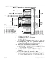
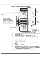
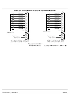
Figure 3-34  Opto-Input Equivalent Circuit (Using External Supply)

9

10

11

12

13

14

15

16

Opto Input 2

Opto Input 3

Opto Input 4

Opto Input 5

Opto Input 6

Opto Input 7

J1

Terminal Tightening Torque = 7 Lb-in (0.8 Nm).

Opto Input 8

Opto Input 9

39

40

17

8

Opto Input 1

*

  User VCC = 10 - 30VDC

External Power Source

*

 User VCC (–)

*

 User VCC (+)

9

10

11

12

13

14

15

16

Opto Input 2

Opto Input 3

Opto Input 4

Opto Input 5

Opto Input 6

Opto Input 7

J1

Opto Input 8

Opto Input 9

39

40

17

8

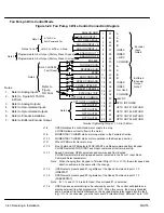
Opto Input 1

*

 User VCC (+)

*

 User VCC (–)

Opto Inputs Closing to Ground

Opto Inputs Closing to +VCC

Содержание 18H Series

Страница 1: ...SERIES 18H AC Flux Vector Control Installation Operating Manual 9 97 MN718 VECTOR DRIVE ...

Страница 2: ... 3 7 Load Reactors 3 7 Input Current Requirements 3 9 AC Main Circuit 3 10 Protection Devices 3 10 Power Disconnect 3 10 Wire Size and Protection Devices 3 10 AC Line Connections 3 13 380 400 VAC Configuration 3 13 Three Phase Input Power 3 15 Single Phase Input Power Considerations 3 18 Single Phase Control Derating 3 18 Size A and B Single Phase Power Installation 3 18 Size C and D Single Phase ...

Страница 3: ...d Outputs 3 47 Analog Inputs 3 47 Analog Outputs 3 50 External Trip Input 3 51 Opto Isolated Inputs 3 51 Opto Isolated Outputs 3 53 Pre Operation Checklist 3 55 Power Up Procedure 3 56 Section 4 Programming and Operation 4 1 Overview 4 1 Display Mode 4 2 Adjusting Display Contrast 4 2 Display Mode Screens 4 3 Display Screens Diagnostic Information Access 4 4 Fault Log Access 4 5 Program Mode 4 6 P...

Страница 4: ... Cures 5 11 Special Drive Situations 5 14 Drive Power Lines 5 14 Radio Transmitters 5 14 Control Enclosures 5 15 Special Motor Considerations 5 15 Wiring Practices 5 16 Optical Isolation 5 17 Plant Ground 5 17 Section 6 Manual Tuning the Series 18H Control 6 1 Manually Tuning the Control 6 1 Motor Mag Amps Parameter 6 1 Slip Frequency Parameter 6 1 Current Prop Gain Parameter 6 1 Current Int Gain ...

Страница 5: ...g Torque Specifications 7 6 Dimensions 7 10 Size A Control 7 10 Size A Control Through Wall Mounting 7 11 Size B Control 7 12 Size B Control Through Wall Mounting 7 13 Size C Control 7 14 Size D Control 7 15 Size E Control 7 16 Size E Control Through Wall Mounting 7 17 Size F Control 7 19 Size F Control Through Wall Mounting 7 20 Size G Control 7 22 Appendix A A 1 Dynamic Braking DB Hardware A 1 R...

Страница 6: ...ee Phase Input Power 5 Connect the encoder refer to Section 3 Encoder Installation 6 Install Dynamic brake hardware if required Refer to Section 3 Optional Dynamic Brake Hardware Quick Start Checklist Check of electrical items CAUTION After completing the installation but before you apply power be sure to check the following items 1 Verify AC line voltage at source matches control rating 2 Inspect...

Страница 7: ...te preset values for the parameters that are necessary for control operation 8 Disconnect the motor from the load including coupling or inertia wheels If the load cannot be disconnected refer to Section 6 and manually tune the control After manual tuning perform steps 10 11 15 16 and 17 WARNING The motor shaft will rotate during this procedure Be certain that unexpected motor shaft movement will n...

Страница 8: ...otor is calculated from the slip frequency and the mechanical speed of the rotor This provides instantaneous adjustment of the voltage and current phasing in response to speed and position feedback from an encoder mounted to the motors shaft The control s rated horsepower is based on the use of a NEMA design B four pole motor and 60Hz operation at nominal rated input voltage If any other type of m...

Страница 9: ... installation and removal inconvenience or consequential damage including injury to any person or property caused by items of our manufacture or sale Some states do not allow exclusion or limitation of incidental or consequential damages so the above exclusion may not apply In any event BALDOR s total liability under all circumstances shall not exceed the full purchase price of the control Claims ...

Страница 10: ...whenever input power is applied and a RUN FWD or REV command is issued If an automatic restart of the motor could cause injury to personnel the automatic restart feature should be disabled by changing the Level 2 Miscellaneous block Restart Auto Man parameter to Manual WARNING Be sure the system is properly grounded before applying power Do not apply AC power before you ensure that all grounding i...

Страница 11: ...the control The control is tested at the factory for high voltage leakage resistance as part of Underwriter Laboratory requirements Caution Do not connect AC power to the Motor terminals T1 T2 and T3 Connecting AC power to these terminals may result in damage to the control Caution Baldor recommends not using Grounded Leg Delta transformer power leads that may create ground loops and degrade syste...

Страница 12: ...nstallation 1 For effective cooling and maintenance the control should be mounted vertically on a flat smooth non flammable vertical surface Table 3 1 lists the Watts Loss ratings for enclosure sizing 2 At least two inches clearance must be provided on all sides for air flow 3 Front access must be provided to allow the control cover to be opened or removed for service and to allow viewing of the K...

Страница 13: ...gh the Wall mounting kit must be purchased These kits are Kit No Description KT0000A00 Size A control through the wall mounting kit KT0001A00 Size B control through the wall mounting kit V0083991 Size E control through the wall mounting kit V0084001 Size F control through the wall mounting kit Procedure 1 Refer to Section 7 of this manual for drawings and dimensions of the through the wall mountin...

Страница 14: ...the 4 mounting holes marked A and the large knockout marked B 4 Drill four 29 mounting holes A Thread each hole using an 8 32 tap 5 Locate the 1 1 4 knockout center B and punch using the manufacturers instructions 6 Debur knockout and mounting holes making sure the panel stays clean and flat 7 Apply RTV to the 4 holes marked A 8 Assemble the keypad to the panel Use 8 32 screws nuts and lock washer...

Страница 15: ... protection System Grounding Baldor Controls are designed to be powered from standard three phase lines that are electrically symmetrical with respect to ground System grounding is an important step in the overall installation to prevent problems The recommended grounding method is shown in Figure 3 1 Caution Baldor recommends not using Grounded Leg Delta transformer power leads that may create gr...

Страница 16: ...ies H controls require a minimum line impedance of 3 Refer to Line Impedance for additional information S If the feeder or branch circuit that provides power to the control has permanently connected power factor correction capacitors an input AC line reactor or an isolation transformer must be connected between the power factor correction capacitors and the control S If the feeder or branch circui...

Страница 17: ...ltsFull Load Speed VoltsNo Load Speed 100 2 Calculate the short circuit current capacity of the power line If the short circuit current capacity is greater than the published maximum short circuit current ratings for the control a line reactor should be installed Two methods of calculating short circuit current capacity are provided A Method 1 Calculate short circuit current as follows ISC KVAXFMR...

Страница 18: ...d with 60Hz power Use 314 if input power is 50Hz Load Reactors Line reactors may be used at the control output to the motor When used this way they are called Load Reactors Load reactors serve several functions that include S Protect the control from a short circuit at the motor S Limit the rate of rise of motor surge currents S Slowing the rate of change of power the control delivers to the motor...

Страница 19: ...500 ZD18H215 E EO or ER 1900 ZD18H415 E EO or ER 1000 ZD18H540 EO or ER 1800 ZD18H215L ER 1900 ZD18H415L ER 1000 ZD18H550 EO or ER 2200 ZD18H220 EO or ER 2400 ZD18H420 EO or ER 1200 ZD18H560 EO or ER 2700 ZD18H220L ER 2100 ZD18H420L ER 1200 ZD18H575 EO or ER 3300 ZD18H225 EO or ER 2800 ZD18H425 EO or ER 1400 ZD18H5100 EO or ER 4200 ZD18H225L ER 2500 ZD18H425L ER 1400 ZD18H5150V EO or ER 4800 ZD18H...

Страница 20: ...7 ZD18H215 E 42 ZD18H415 E 21 ZD18H525 EO or ER 32 ZD18H215 EO or ER 54 ZD18H415 EO or ER 27 ZD18H530 EO or ER 41 ZD18H220 EO or ER 68 ZD18H415L ER 27 ZD18H540 EO or ER 52 ZD18H220L ER 60 ZD18H420 E or ER 34 ZD18H550 EO or ER 62 ZD18H225 EO or ER 80 ZD18H420L ER 30 ZD18H560 EO or ER 62 ZD18H225L ER 75 ZD18H425 EO or ER 40 ZD18H575 EO 100 ZD18H230 EO or ER 104 ZD18H425L ER 38 ZD18H5100 EO 125 ZD18H...

Страница 21: ...ss FRS Very Fast Action 230 VAC Buss JJN 460 VAC Buss JJS 575 VAC Buss JJS Time Delay Fuses 230 VAC Buss FRN 460 VAC Buss FRS to 600A KTU 601 1200A 575 VAC Buss FRS to 600A KTU 601 1200A Power Disconnect A power disconnect should be installed between the input power service and the control for a fail safe method to disconnect power The control will remain in a powered up condition until all input ...

Страница 22: ...A 60A 45A 6 16 40 60A 80A 60A 4 25 50 70A 100A 75A 4 25 60 90A 125A 90A 2 35 75 125A 150A 125A 1 0 54 100 150A 200A 150A 2 0 70 125 175A 250A 175A 2 0 70 150 200A 300A 200A 4 0 120 200 250A 350A 250A 2 1 0 2 54 250 350A 450A 350A 2 3 0 2 95 300 400A 500A 400A 2 4 0 2 120 350 500A 600A 500A 3 4 0 3 120 400 600A 800A 600A 3 250 mcm 3 125 450 600A 800A 600A 3 250 mcm 3 125 500 800A 1000A 800A 3 350 m...

Страница 23: ...14 2 5 7 5 10A 15A 10A 14 2 5 10 15A 15A 12A 14 2 5 15 20A 25A 20A 12 4 20 25A 35A 25A 10 6 25 30A 40A 30A 8 10 30 35A 50A 35A 8 10 40 45A 60A 45A 6 16 50 60A 80A 60A 4 25 60 70A 90A 70A 4 25 75 120A 150A 120A 3 27 100 120A 150A 120A 1 0 54 125 150A 200A 150A 2 0 70 150 175A 225A 175A 2 0 70 Note All wire sizes based on 75 C copper wire 3 line impedance Higher temperature smaller gauge wire may be...

Страница 24: ...4HP 10HP 208VAC 230VAC 9 04HP Likewise a 10HP 460VAC control operating at 380VAC has a reduced power rating of 8 26HP 10HP 380VAC 460VAC 8 26HP To obtain the full output rating of 10HP in either case requires a 15HP Control 380 400 VAC Configuration Size A and B controls may be used directly with a 380 400 VAC power source control modification is not necessary Size C D E F and G controls all requi...

Страница 25: ...all power sources from the control If power has been applied wait at least 5 minutes for bus capacitors to discharge 3 Remove or open the front cover 4 Remove the wires from the two right side terminals 5 Place the wires on the center terminals as shown 6 Install or close the front cover Figure 3 2 Configuring the Control Transformer Terminal Block for 380 400 VAC Size G 460VAC 380 400VAC ...

Страница 26: ...ground loops and degrade system performance Instead we recommend using a four wire Wye 1 Connect the incoming AC power wires from the protection devices to L1 L2 and L3 at the Main Circuit Terminals The phase rotation is not important as the control is not phase sensitive 2 Connect earth ground to the of the control Be sure to comply with local codes Note Use same gauge wire for earth ground as is...

Страница 27: ...9 M Enable J1 Motor M M M M Contactor To Power Source Rated Coil Voltage M Contacts of optional M Contactor Note Close Enable after M contact closure Notes 1 See Protective Devices described previously in this section 2 Shield wires inside a metal conduit 3 Metal conduit should be used to shield output wires between control and motor Connect conduits so the use of Load Reactor or RC Device does no...

Страница 28: ...3 8 Single Phase Rating Wire Size and Protection Devices 460 VAC Controls Control Output P R ti Input Breaker Input Fuse Wire Gauge p Power Rating p Fast Acting Time Delay AWG mm2 1 15A 4A 4A 14 2 5 2 15A 8A 8A 14 2 5 3 15A 10A 10A 14 2 5 5 15A 15A 15A 14 2 5 7 5 15A 15A 15A 14 2 5 10 20A 15A 15A 14 2 5 15 25A 25A 25A 14 2 5 20 30A 30A 30A 14 2 5 25 35A 30A 30A 14 2 5 30 40A 40A 40A 10 6 40 60A 50...

Страница 29: ... 1 2 HP 230 and 460 VAC controls No derating required 2 3 15 HP Size B 230 and 460 VAC controls Derate HP by 40 of the nameplate rating 3 15 HP Size C and Larger 230 and 460 VAC controls Derate HP by 50 of the nameplate rating Size A and B Single Phase Power Installation Jumper Configuration Size A and B controls no jumper changes required Power and Control Connections The single phase power and m...

Страница 30: ... J1 8 at least 20 msec before the main M contacts open to prevent arcing at contacts This greatly increases contactor life and allows use of IEC rated contactors Optional Connection of Load Reactor and M Contactor L1 L2 Fuse Connection Note 1 L1 L2 L1 L2 L3 Circuit Breaker Earth Optional components not provided with 18H Control AC Motor See Recommended Tightening Torques in Section 7 Note 2 Baldor...

Страница 31: ... Terminals L2 and L3 2 Place a jumper across control power input terminals L1 and L2 Use the same size wire for the jumper as the incoming power wires on L2 and L3 3 Connect earth ground to the of the control Be sure to comply with local codes Note Use same gauge wire for earth ground as is used for L1 L2 and L3 connections Refer to the Wire Size and Protection Devices tables shown previously in t...

Страница 32: ... J1 8 at least 20 msec before the main M contacts open to prevent arcing at contacts This greatly increases contactor life and allows use of IEC rated contactors Optional Connection of Load Reactor and M Contactor L1 L2 Fuse Connection Note 1 L1 L2 L1 L2 L3 Circuit Breaker Earth Optional components not provided with 18H Control AC Motor See Recommended Tightening Torques in Section 7 Note 2 Baldor...

Страница 33: ...a jumper across control power input terminals L2 and L3 Use the same size wire for the jumper as the incoming power wires on L1 and L2 3 Connect earth ground to the of the control Be sure to comply with local codes Note Use same gauge wire for earth ground as is used for L1 L2 and L3 connections Refer to the Wire Size and Protection Devices tables shown previously in this section 4 Connect the thr...

Страница 34: ...J1 8 at least 20 msec before the main M contacts open to prevent arcing at contacts This greatly increases contactor life and allows use of IEC rated contactors Optional Connection of Load Reactor and M Contactor L1 L2 Fuse Connection Note 1 L1 L2 L1 L2 L3 Circuit Breaker Earth Optional components not provided with 18H Control AC Motor See Recommended Tightening Torques in Section 7 Note 2 Baldor ...

Страница 35: ...inals L1 and L3 Use the same size wire for the jumper as the incoming power wires on L2 and L3 3 Connect earth ground to the of the control Be sure to comply with local codes Note Use same gauge wire for earth ground as is used for L1 L2 and L3 connections Refer to the Wire Size and Protection Devices tables shown previously in this section 4 Connect the three phase power leads of the AC motor to ...

Страница 36: ...J1 8 at least 20 msec before the main M contacts open to prevent arcing at contacts This greatly increases contactor life and allows use of IEC rated contactors Optional Connection of Load Reactor and M Contactor L1 L2 Fuse Connection Note 1 L1 L2 L1 L2 L3 Circuit Breaker Earth Optional components not provided with 18H Control AC Motor See Recommended Tightening Torques in Section 7 Note 2 Baldor ...

Страница 37: ...ure must not exceed 80 C 1 Select a clean VERTICAL surface that is free from corrosive gasses liquids vibration dust and metallic particles Caution If the DB hardware mounting is in any position other than vertical Figure 3 11 the DB hardware must be derated by 35 of its rated capacity 2 Mount the DB hardware as shown in Figure 3 11 Figure 3 11 DB Hardware Installation É É É É É É É É É É É É É É ...

Страница 38: ...suffix R2 B R1 B EO or MO suffix B B GND D1 D2 GND ER suffix R2 B R1 B GND Figure 3 13 Wiring for RGA Assembly See recommended Terminal Tightening Torques in Table 3 10 Optional Customer Supplied Breaker or Fuse Protection Subject to Local Codes MOTOR 50 60 Hz 3 Phase Power GND R2 B R1 T3 T2 T1 L3 L2 L1 GND GND T1 T2 T3 Optional Dynamic Brake RGA Control Terminals DB Terminals R2 R1 Note Although ...

Страница 39: ...rminals DB Terminals Note Although not shown metal conduit should be used to shield all power wires and motor leads Figure 3 15 Wiring for RTA Assembly See recommended Terminal Tightening Torques in Section 7 See recommended Terminal Tightening Torques in Table 3 10 Optional Customer Supplied Breaker or Fuse Protection Subject to Local Codes MOTOR 50 60 Hz 3 Phase Power GND B B T3 T2 T1 L3 L2 L1 G...

Страница 40: ... and R1 R2 Terminals D1 D2 Terminals Control Voltage Rating VAC Braking Option Watts Rating Wire SIze Volt Tightening Torque Wire SIze Volt Tightening Torque g AWG mm2 Volt Nm Lb in AWG mm2 Volt Nm Lb in 230 10 000 10 6 600 2 26 32 20 22 0 5 600 0 4 3 5 230 10 000 8 10 600 2 26 32 20 22 0 5 600 0 4 3 5 460 20 000 10 6 600 2 26 32 20 22 0 5 600 0 4 3 5 460 20 000 8 10 600 2 26 32 20 22 0 5 600 0 4 ...

Страница 41: ...ct all shields to J1 30 To do this solder a Drain Wire from each shield to the wire soldered to the braided shield in step 2 4 Insulate or tape off ungrounded end of shields to prevent contact with other conductors or ground Encoder End 1 Strip the outside jacket approximately 0 375 9 5mm from the end 2 Identify each of the four twisted pair and label or use the color codes shown in Figure 3 17 fo...

Страница 42: ...es insulation in J1 terminals as proper electrical connection may not be made 1 Feed the control end of the cable through one of the Knock out holes in the control case so connections can be made inside the control 2 Differential Connections Connect the cable braided shield to J1 30 at control end Connect the cable ends as follows See Figure 3 17 Encoder End Control End A J1 23 A H J1 24 A B J1 25...

Страница 43: ...ed solid state switch or limit switch should be wired as shown in Figure 3 18 Regardless of the type of switch used clean rising and falling edges at J1 27 are required for accurate positioning Note Control requires dynamic brake hardware for Orient Homing function to work Control will trip without dynamic brake hardware installed Size A and B controls E suffix are shipped with factory installed d...

Страница 44: ...he Serial operating mode requires one of the optional Serial Interface expansion boards RS232 or 422 485 Installation and operation information for these serial expansion boards is provided in Serial Communications expansion board manual MN1310 This manual is shipped with the serial expansion boards Keypad Mode Connections To operate in the Keypad mode set the Level 1 Input block Operating Mode pa...

Страница 45: ...TURN OPTO OUT 4 RETURN COMMON A A B B INDEX INDEX Not Used Encoder Input Note 3 Buffered Encoder Output Note 4 INPUT 1 INPUT 7 6 Note 1 Notes 1 Refer to Analog Outputs 2 Refer to Opto Isolated Outputs 3 Refer to Encoder Installation 4 Refer to Buffered Encoder Outputs Refer to Figure NO TAG J1 8 Optional is active when Level 2 Protection block Local Enable INP parameter is set to ON OPEN disables ...

Страница 46: ...ntrol is operated by the opto Isolated inputs at J1 8 through J1 16 and the analog command input The opto inputs can be switches as shown in Figure 3 21 or logic signals from another device The External Trip opto input at J1 16 is active if connected as shown and the Level 2 Protection block External Trip parameter is set to ON ...

Страница 47: ...es the control and motor coasts to a stop CLOSED allows current to flow in the motor and produce torque J1 9 MOMENTARY CLOSED starts motor operation in the Forward direction In JOG mode J1 12 CLOSED continuous CLOSED jogs motor in the Forward direction J1 10 MOMENTARY CLOSED starts motor operation in the Reverse direction In JOG mode J1 12 CLOSED CONTINUOUS closed JOGS motor in the Reverse directi...

Страница 48: ...allow selection of 15 preset speeds and provide Fault Reset as defined in Table 3 12 Table 3 12 Switch Truth Table for 15 Speed 2 Wire Control Mode Function J1 11 J1 12 J1 13 J1 14 Preset 1 Open Open Open Open Preset 2 Closed Open Open Open Preset 3 Open Closed Open Open Preset 4 Closed Closed Open Open Preset 5 Open Open Closed Open Preset 6 Closed Open Closed Open Preset 7 Open Closed Closed Ope...

Страница 49: ...ult Reset Notes 1 Refer to Analog Outputs 2 Refer to Opto Isolated Outputs 3 Refer to Encoder installation 4 Refer to Buffered Encoder Output Refer to Figure NO TAG J1 8 OPEN disables the control motor coasts to a stop CLOSED allows current to flow in the motor and produce torque J1 9 CLOSED operates the motor in the Forward direction with J1 10 open OPEN motor decels to stop depending on Keypad S...

Страница 50: ...e control and motor coasts to a stop CLOSED allows current to flow in the motor J1 9 CLOSED starts motor operation in the Forward direction OPEN initiates Stop command J1 10 CLOSED starts motor operation in the Reverse direction OPEN initiates Stop command J1 11 OPEN selects setting of Command Select parameter Closed selects Analog Input 1 Note If Command Select Level 1 Input block is set to Poten...

Страница 51: ...Not Used Encoder Input Note 6 Buffered Encoder Output Note 7 Refer to Figure NO TAG J1 8 OPEN disables the control and motor coasts to a stop CLOSED allows current to flow in the motor J1 9 MOMENTARY CLOSED starts motor operation in the Forward direction J1 10 MOMENTARY CLOSED starts motor operation in the Reverse direction J1 11 When OPEN motor Decels to stop J1 12 Run Command OPEN selects STOP S...

Страница 52: ...s instructed in Section 3 of this manual This creates and saves the first parameter set which is numbered Table 0 3 Set switches J1 13 and J1 14 to Parameter Table 1 Be sure switches J1 9 and J1 10 are OPEN J1 8 is CLOSED Enter all parameter values and autotune as instructed in Section 3 of this manual This creates and saves the second parameter set which is numbered Table 1 4 Set switches J1 13 a...

Страница 53: ... NO TAG for 4 20mA 5 Refer to Encoder installation 6 Refer to Buffered Encoder Output Refer to Figure NO TAG J1 8 OPEN disables the control motor coasts to a stop CLOSED allows current to flow in the motor and produce torque J1 9 CLOSED to enable operation in the Forward direction OPEN TO DISABLE Forward operation drive will brake to a stop if a Forward command is still present J1 10 CLOSED to ena...

Страница 54: ...sion board Selections are shown in Figure 3 26 2 Level 2 Process Control block Setpoint Source parameter must be set to the type of set point being used A A fixed value setpoint is a keypad programmed parameter value To program a fixed setpoint do the following i Set the Level 2 Process Control block Setpoint Source parameter to Setpoint CMD ii Set the Level 2 Process Control block Setpoint CMD pa...

Страница 55: ...t EXB 10 Volt EXB 4 20mA EXB 3 15 PSI EXB Tachometer EXB Serial None Available sources are Potentiometer 10 Volts 5 Volts 4 20 mA 5 Volt EXB 10 Volt EXB 4 20mA EXB 3 15 PSI EXB Tachometer EXB None Closed When Process Mode is Enabled J1 13 ACC DEC S Curve Profiler Differentiator EXB Pulse Follower Only s s Proportional Gp Gp Proportional Differential Differential Amp Gd s Gd s Integral Integral Mot...

Страница 56: ... or Feedback Requires expansion board EXB001A01 RS232 Serial Communication EXB or Requires expansion board EXB002A01 RS422 RS485 High Speed Serial Communication EXB Conflicting inputs Do not use same input signal multiple times ËËË ËËË Conflicting level 1 or 2 expansion boards Do not use Specific Process Mode Outputs Process Mode Only Analog Monitoring Outputs Name Description Process FDBK Process...

Страница 57: ... 3 30 for 4 20mA 5 Refer to Encoder installation 6 Refer to Buffered Encoder Output J1 8 OPEN disables the control motor coasts to a stop Closed allows current to flow in the motor and produce torque J1 9 CLOSED operates the motor in the Forward direction with J1 10 open OPEN motor decels to stop depending on Keypad Stop mode parameter setting J1 10 CLOSED operates motor in the Reverse direction w...

Страница 58: ...2 Analog Output 1 Analog Output 2 Command Pot or 0 10VDC 5VDC 10VDC or 4 20 mA Input 5KW Programmable 0 5VDC Factory Preset Speed Programmable 0 5VDC Factory Preset Current Terminal Tightening Torque 7 Lb in 0 8 Nm Analog Input 1 The single ended analog input 1 is used when the controller is set to Standard 3 Wire Fan Pump 2 or 3 Wire Process or Bipolar Control not Keypad or 15 Speed 2 Wire modes ...

Страница 59: ...pins 1 2 Refer to Figure NO TAG for jumper position information Note Analog Input 2 can be connected for single ended operation by grounding either of the inputs provided the common mode voltage range is not exceeded The common mode voltage can be measured with a voltmeter Apply the maximum command voltage to analog input 2 J1A 4 5 Measure the AC and DC voltage across J1A 1 to J1A 4 Add the AC and...

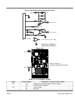
Страница 60: ...Amps are TL082 or TL084 Analog Ground is separated from Chassis Ground Electrically they are separated by an RC network 30KW 15VDC J1 2 3 4 5 1 Figure 3 30 JP2 JP1 Refer to Table 3 15 for jumper placement information 1 2 3 1 2 3 Table 3 15 Control Board Jumper Jumper Jumper Position Description of Jumper Position Setting JP1 1 2 Voltage Speed Command Signal Factory Setting 2 3 4 20mA input at Anal...

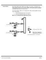
Страница 61: ...G of Section 4 of this manual The return for these outputs is J1 1 analog ground Each output is programmed in the Level 1 Output block 1 Connect the Output 1 wires to J1 6 and J1 1 2 Connect the Output 2 wires to J1 7 and J1 1 Figure 3 31 Analog Outputs Equivalent Circuits 10KW 10KW 033 mf 50W 6 From Microprocessor 10KW 10KW 033 mf 50W 7 From Microprocessor Notes All OP Amps are TL082 or TL084 Ana...

Страница 62: ...re Relay T1 T2 T3 T1 T2 T3 G Motor M M M 16 17 J1 External Trip External or remote motor overload protection may be required by National Electrical Code or equivalent Do not run these wires in same conduit as motor leads or AC power wiring Customer Provided Source Voltage Motor Thermostat Leads CR1 Optional hardware Must be ordered separately Note Add appropriately rated protective device for AC r...

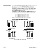
Страница 63: ...pto Input 6 Opto Input 7 J1 Terminal Tightening Torque 7 Lb in 0 8 Nm Opto Input 8 Opto Input 9 39 40 17 8 Opto Input 1 User VCC 10 30VDC External Power Source User VCC User VCC 9 10 11 12 13 14 15 16 Opto Input 2 Opto Input 3 Opto Input 4 Opto Input 5 Opto Input 6 Opto Input 7 J1 Opto Input 8 Opto Input 9 39 40 17 8 Opto Input 1 User VCC User VCC Opto Inputs Closing to Ground Opto Inputs Closing ...

Страница 64: ... relay coil See Electrical Noise Considerations in Section 5 of this manual 1 Connect OPTO OUT 1 wires to J1 19 and J1 41 2 Connect OPTO OUT 2 wires to J1 20 and J1 42 3 Connect OPTO OUT 3 wires to J1 21 and J1 43 4 Connect OPTO OUT 4 wires to J1 22 and J1 44 Each Opto Output is programmed in the Output programming block Figure 3 35 Opto isolated Output Configurations Terminal Tightening Torque 7 ...

Страница 65: ...alent Circuit 19 20 21 22 41 42 43 Opto Output 1 Opto Output 2 Opto Output 3 Opto Output 4 Opto Out 1 Return J1 Terminal Tightening Torque 7 Lb in 0 8 Nm Opto Out 2 Return Opto Out 3 Return 44 Opto Out 4 Return 18 PC865 50mA max 10 30VDC Opto Outputs PC865 50mA max PC865 50mA max PC865 50mA max ...

Страница 66: ...nected to earth ground 4 Check all signal wiring for accuracy 5 Be certain all brake coils contactors and relay coils have noise suppression This should be an R C filter for AC coils and reverse polarity diodes for DC coils MOV type transient suppression is not adequate WARNING Make sure that unexpected operation of the motor shaft during start up will not cause injury to personnel or damage to eq...

Страница 67: ...ps FLA Motor Rated Speed base speed Motor Rated Frequency Motor Mag Amps no load current Encoder Counts 7 Go to Level 2 Motor Data block press ENTER at CALC PRESETS select YES using the key and let the control calculate preset values for the parameters that are necessary for control operation 8 Disconnect the motor from the load including coupling or inertia wheels If the load cannot be disconnect...

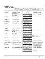
Страница 68: ...de all other external commands to the J1 terminal strip will be ignored with the exception of the external trip input DISP Press DISP to return to display mode from programming mode Provides operational status and advances to the next display menu item including the diagnostic screens SHIFT Press SHIFT in the program mode to control cursor movement Pressing the SHIFT key once moves the blinking cu...

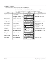
Страница 69: ...ese tasks are described on the following pages Adjusting Display Contrast When AC power is applied to the control the keypad should display the status of the control If there is no visible display use the following procedure to adjust the contrast of the display Contrast may be adjusted in display mode when motor is stopped or running Action Description Display Comments Apply Power No visible disp...

Страница 70: ...mote serial mode press local for this display Press DISP key Display mode custom unit output rate only if Level 2 Custom Units block parameters are set Press DISP key Display Frequency First Display Mode Screen Press DISP key DIsplay Current Press DISP key DIsplay Voltage Press DISP key Combined DIsplay Press DISP key Screen to enter Fault Log Press DISP key Screen to enter Diagnostic Menu Press D...

Страница 71: ...current remaining Press DISP key Display mode showing opto inputs outputs states Opto Inputs states Left Opto Outputs states Right Press DISP key Display mode showing actual drive running time HR MIN SEC format Press DISP key Display mode showing operating zone voltage and control type Typical display Press DISP key Display mode showing continuous amps PK amps rating amps volt scale of feedback po...

Страница 72: ... to make room for the newest fault To access the fault log perform the following procedure Action Description Display Comments Apply Power Logo display for 5 seconds Display mode showing motor speed Display mode Press DISP key 5 times Scroll to the Fault Log screen Fault Log access screen Press ENTER key Display first fault type and time fault occurred Most recent fault displayed Press key Scroll ...

Страница 73: ... is operating If the parameter is displayed with an L the value is locked and the security access code must be entered before its value can be changed Parameter Blocks Access for Programming Use the following procedure to access parameter blocks to program the control Action Description Display Comments Apply Power Keypad Display shows this opening message Logo display for 5 seconds If no faults a...

Страница 74: ...If no faults and programmed for LOCAL operation Display mode Stop LED on Press PROG key Access programming mode Press Y or B key Scroll to Level 1 Input Block Press ENTER to access INPUT block parameter Press ENTER key Access Input Block Keypad mode shown is the factory setting Press ENTER key Access Operating Mode parameter Keypad mode shown is the factory setting Press Y key Scroll to change sel...

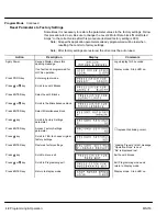
Страница 75: ...pening message Logo display for 5 seconds If no faults and programmed for LOCAL operation Display mode Stop LED on Press PROG key Enter program mode Press Y or B key Scroll to Level 2 Blocks Press ENTER key Select Level 2 Blocks Press Y or B key Scroll to the Miscellaneous block Press ENTER key Select Miscellaneous block Press Y key Scroll to Factory Settings parameter Press ENTER key Access Facto...

Страница 76: ...us block Press Y key Scroll to Factory Settings parameter Press ENTER key Access Factory Settings parameter V represents blinking cursor Press Y key Scroll to YES to choose original factory settings Press ENTER key Restores factory settings Loading Presets is first message Operation Done is next No is displayed last Press Y key Scroll to menu exit Press ENTER key Return to display mode Display mod...

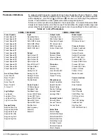
Страница 77: ...mal Places Setpoint Command Preset Speed 10 Opto Output 2 Value at Speed Set PT ADJ Limit Preset Speed 11 Opto Output 3 Units of Measure Process ERR TOL Preset Speed 12 Opto Output 4 Process PROP Gain Preset Speed 13 Zero SPD Set PT Protection Process INT Gain Preset Speed 14 At Speed Band Overload Process DIFF Gain Preset Speed 15 Set Speed External Trip Follow I O Ratio Analog Out 1 Local Enable...

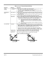
Страница 78: ... 1 and S Curve 1 are associated together Likewise Accel 2 Decel 2 and S Curve 2 are associated together These associations can be used to control any Preset Speed or External Speed command command Note If drive faults occur during rapid Accel or Decel selecting an S curve may eliminate the faults JOG SETTINGS Jog Speed Jog Speed is the programmed speed used during for jog Jog can be initiated from...

Страница 79: ...nsidered Current loop allows long cable lengths without attenuation of the command signal 10 VOLT W TORQ FF when a differential command is present at J1 4 and 5 allows addi tional 5V torque feedforward input at J1 1 2 and 3 to set a predetermined amount of torque inside the rate loop with high gain settings EXB PULSE FOL selects optional Master Pulse Reference Isolated Pulse Follower ex pansion bo...

Страница 80: ...oning command when control is within the position band parameter tolerance Over Temp Warn Active when control heat sink is within 3 C of Int Overtemp Process Error Active when process feedback signal is outside the range specified by the Level 2 Process Control block AT Setpoint Band parameter Turns off when process feedback error is eliminated Drive Run Active when drive is Ready Enabled Speed or...

Страница 81: ... to diagnose control problems AC Voltage A scaled AC waveform that represents the AC line to line motor terminal voltage 0V Neg Peak PWM voltage 2 5V centered 5V Pos Peak PWM voltage At rated motor voltage a full 0 to 5V sinusoidal waveform should be present This waveform should be at or greater than the motor base frequency At half the motor base frequency a 1 25V to 3 75 sine wave is present Bus...

Страница 82: ...cal direction of rotation to match that of the motor Sets the current loop proportional gain Sets the current loop integral gain Sets the speed velocity loop proportional gain Sets the speed velocity loop integral gain Sets the speed velocity loop differential gain Sets the position loop proportional gain Sets the rated slip frequency of the motor Stator R1 Stator resistance in ohms If set too hig...

Страница 83: ...d number right most is the motor RPM corresponding to the units in the first number A decimal may be inserted into the numbers by placing the flashing cursor over the up down arrow Allows user specified units of measure to be displayed on the Output Rate display Use the shift and arrow keys to scroll to the first and successive characters If the character you want is not displayed move the flashin...

Страница 84: ...al Table 4 3 Level 2 Parameter Block Definitions Continued Block Title Parameter Description MISCELLANEOUS Restart Auto Man Manual If a fault or power loss occurs the control must be manually reset to resume operation Automatic If a fault or power loss occurs the control will automatically reset to resume operation Restart Fault Hr The maximum number of automatic restart attempts before requiring ...

Страница 85: ...nto the program Mode within this time limit the security Access Code does not have to be re entered This timer starts when leaving the Program Mode by pressing DISP Access Code A 4 digit number code Only persons that know the code can change secured Level 1 and Level 2 parameter values Note Please record your access code and store it in a safe place If you cannot gain entry into parameter values t...

Страница 86: ...h the process input is compared The result is that if the process input is within the comparison band the corresponding Opto Output will become active Sets the PID loop proportional gain This determines how much adjustment to motor speed within the Set PT ADJ Limit is made to move the analog input to the setpoint Sets the PID loop Integral gain This determines how quickly the motor speed is adjust...

Страница 87: ...perform Auto Tune Always run CALC Presets as the first step of Auto Tune This procedure trims out voltage offsets for the differential analog input at J1 4 and J1 5 Measures current response to pulses of one half the rated motor current Measures motor stator resistance Sets motor magnetizing current by running motor at near rated speed Checks the values for Encoder Lines per revolution and encoder...

Страница 88: ...e yourself with the following information before attempting any troubleshooting or service of the control Most troubleshooting can be performed using only a digital voltmeter having an input impedance exceeding 1 meg Ohm In some cases an oscilloscope with 5 MHZ minimum bandwidth may be useful Before consulting the factory check that all power and control wiring is correct and installed per the rec...

Страница 89: ...ols Logic Supply FLT Logic power supply not working properly Lost User Data Battery backed RAM parameters have been lost or corrupted When fault cleared Reset the control will reset to factory preset values Low INIT Bus V Insufficient bus voltage on startup Memory Error EEPROM error occurred Contact Baldor New Base ID Control board was changed since last operation No Faults Fault log is empty No E...

Страница 90: ...croll to the Fault Log entry point Press ENTER key Display first fault type and time fault occurred Typical display Press Y key Scroll through fault messages If no messages the fault log exit choice is displayed Press ENTER key Return to display mode Display mode stop key LED is on How to Clear the Fault Log Use the following procedure to clear the fault log Action Description Display Comments App...

Страница 91: ...urrent remaining Press DISP key Display showing opto inputs outputs states Opto Inputs states Left Opto Outputs states Right Press DISP key Display showing actual drive running time HR MIN SEC format Press DISP key Display showing operating zone voltage and control type Press DISP key Display showing continuous amps PK amps rating amps volt scale of feedback power base ID ID is displayed as a hexa...

Страница 92: ...nsor Defective current sensor Replace current sensor DC Bus High Excessive dynamic braking power Increase the DECEL time Check dynamic brake watt and resistance parameter values Add optional dynamic braking hardware Dynamic brake wiring problem Check dynamic brake hardware wiring Input voltage too high Verify proper AC line voltage Use step down isolation transformer if needed Use line reactor to ...

Страница 93: ...nect wiring between control and motor Retry test If GND FLT is cleared reconnect motor leads and retry the test Rewire as necessary Repair motor If GND FLT remains contact Baldor INT Over Temp Motor Overloaded Correct motor loading Verify proper sizing of control and motor Ambient temperature too high Relocate control to cooler operating area Add cooling fans or air conditioner to control cabinet ...

Страница 94: ...block Motor Will Not Start Not enough starting torque Increase Current Limit setting Start Motor overloaded Check for proper motor loading Check couplings for binding Verify proper sizing of control and motor Control not in local mode of operation Place control in local mode Motor may be commanded to run below minimum frequency setting Increase speed command or lower minimum frequency setting Inco...

Страница 95: ...rically isolate encoder from motor Install optional Isolated Encoder Feedback expansion board Electrical noise from external DC coils Install reverse biased diodes across all external DC relay coils as shown in the Opto Output circuit examples of this manual See Electrical Noise Considerations in Section 5 of this manual Electrical noise from external AC coils Install RC snubbers on all external A...

Страница 96: ... external AC coils Install RC snubbers on all external AC coils See Electrical Noise Considerations in Section 7 of this manual Excessive load Correct motor load Verify proper sizing of control and motor Excessive power in dynamic brake circuit Verify proper Ohm and Watt parameters of DC Injection Braking Increase decel time Add optional dynamic braking hardware Regen R PWR FLT Incorrect dynamic b...

Страница 97: ...3E 507 W 606 E06 61E E1E 207L E 001 801 407L E 201 A01 510 E 607 E07 61F E1F 210 E 007 807 028 828 410 E 207 A07 207 A07 510 W 607 E07 61F E1F 210 W 028 828 410 W 207 A07 515 E 608 E08 620 E20 210L E 02B 82B 410L E 23F A3F 515 W 608 E08 620 E20 215 E 01A 81A 01A 81A 415 E 22C A2C 242 A42 510L 215 W 01A 81A 415 W 242 A42 515L 210L ER 00C 80C 410L ER 208 A08 520 611 E11 215V 008 808 415V 20E A0E 520...

Страница 98: ...coupling to sensitive circuits All methods are less costly when designed into a system initially than if added after installation Figure 5 1 shows an oscilloscope trace of noise induced as the coil circuit is opened in a 1 ft wire located next to a lead for a Size 2 contactor coil Scope input impedance is 10KW for all scope traces Maximum peak voltage is over 40V Unless well filtered this is often...

Страница 99: ...djacent wire is grounded in a twisted pair shielded cable Note that the vertical scale is 1 V div rather than the 20 V div in figures 5 1 and 5 2 This shows that snubbers and twisted pair shielded wire should be used for sensitive circuits located adjacent to coil wires Figure 5 3 R C Snubber Circuit twisted pair A reverse biased diode across a DC coil achieves the same result as adding an R C snu...

Страница 100: ...f a 10 hp 460 VAC drive Scope is set at 5 V div and 2 msec div Figure 5 5 10HP 460VAC Drive If the shielded pair cable is used the coupling is reduced by nearly 90 Figure 5 6 Figure 5 6 10HP 460VAC Drive Shielded The motor leads of DC motors contain similar voltage transients The switching rate is about 360 times a second These noise transients can produce about 2V of noise induced in a wire adjac...

Страница 101: ...ary to reduce transient voltages in the wires to the motor by adding load reactors Load reactors are installed between the control and motor These are often required where a motor housing lacks the necessary shielding typically linear motors mounted directly to machine frames or where the power wires to motors are contained in flexible cables Reactors are typically 3 reactance and are designed for...

Страница 102: ...the motor frame and ground The severity of these voltages increases with the length of the ground wire Installations with the motor and control mounted on a common frame and with heavy ground wires less than 10 ft long rarely have a problem caused by these motor generated transient voltages Another cure may be needed when the motor frame transient voltages are capacitively coupled to feedback devi...

Страница 103: ...lly originate from speed and torque controls plus DC tachometers and process controllers Reliability is often improved by the following noise reduction techniques Use twisted pair shielded wires with the shield grounded at the drive end only Route analog signal wires away from power or control wires all other wiring types Cross power and control wires at right angles 90 to minimize inductive noise...

Страница 104: ... 100 to 500 V m sec which is adequate for most control logic signals High performance opto couplers with common mode ratings up to 5 000 V m sec are installed for the most severe noise environments Fiber Optics Special plastic fiber strands transmit light over long as well as short distances Because the fibers are immune to electromagnetic energy the use of fiber optic bundles eliminate the proble...

Страница 105: ...Section 1 General Information 5 18 Troubleshooting MN718 ...

Страница 106: ...ing to raise the Motor Mag Amps parameter value will eventually saturate the motor voltage By lowering the Motor Mag Amps parameter value the motor voltage will lower proportionally 5 While the motor is running adjust the Motor Mag Amps parameter until the display indicates the proper voltage 80 of motor rated Slip Frequency Parameter This parameter is located in the Level 1 Vector Control Block T...

Страница 107: ...ation that results in a proportional rate loop This selection is ideal for systems where overshoot must be avoided and substantial stiffness ability of the controller to maintain commanded speed despite varying torque loads isn t required Increasing values of the Speed Int Gain parameter increases the low frequency gain and stiffness of the controller an excessive integral gain setting will cause ...

Страница 108: ... Laplace Operator to denote the integral Output E Kp KI s Kp s Ki Kp s The second equation shows that the ratio of Ki Kp is a frequency in radians sec In the Baldor Series 18H AC Vector Control the integral gain has been redefined to be KI Ki Kp 2p Hz and the transfer function is Output E Kp s 2pKI s This sets the integral gain as a frequency in Hz As a rule of thumb set this frequency about 1 10 ...

Страница 109: ...Section 1 General Information 6 4 Manual Tuning the Series 18H Control MN718 ...

Страница 110: ...60 secs Operating Conditions Voltage Range 230 VAC Models 460 VAC Models 575 VAC Models 180 264 VAC 3O 60 Hz 180 230 VAC 3O 50 Hz 340 528 VAC 3O 60 Hz 340 460 VAC 3O 50 Hz 495 660 VAC 3O 60 Hz Input Line Impedance 3 Minimum Required Ambient Operating Temperature 0 to 40 C Derate Output 2 per C over 40 C to 55 C Max Rated Storage Temperature 30 C to 65 C Enclosure NEMA 1 E and EO suffix Models NEMA...

Страница 111: ...M Velocity Loop Bandwidth Adjustable to 180 Hz Current Loop Bandwidth Adjustable to 1200 Hz Maximum Output Frequency 1000 Hz Quiet Frequency Version Full rating 1 8 KHz PWM frequency Adjustable to 16 KHz with linear derating between 8 16KHz by 30 at 16 KHz Standard Frequency Version Full rating 1 2 5 KHz PWM frequency Adjustable to 5 KHz with linear derating between 2 5 5KHz by 10 at 5 KHz Selecta...

Страница 112: ...e 6 8 K Ohms Leakage Current 10 mA maximum Update Rate 16 msec Digital Outputs Opto isolated Logic Outputs 4 Assignable ON Current Sink 50 mA Max ON Voltage Drop 2 VDC Max Update Rate 33 msec Maximum Voltage 30 VDC Diagnostic Indications Current Sense Fault Regeneration db Overload Following Error Ground Fault Soft Start Fault Encoder Loss Instantaneous Over Current Under Voltage Logic Power Fault...

Страница 113: ...15 11 1 21 36 20 14 9 27 31 10 7 4 15 30 15 11 1 21 24 ZD18H420 EO 460 C 20 14 9 27 54 25 18 6 34 39 15 11 1 21 46 20 14 9 27 31 ZD18H425 EO 460 C 25 18 6 34 58 30 22 3 40 46 20 14 9 27 46 25 18 6 34 39 ZD18H430 EO 460 C 30 22 3 40 70 40 29 8 52 60 25 18 6 35 61 30 22 3 40 46 ZD18H430V EO 460 C 30 22 3 40 100 40 29 8 52 60 30 22 3 40 92 30 22 3 40 46 ZD18H440 EO 460 D 40 29 8 55 100 50 37 2 65 75 ...

Страница 114: ...IC IP HP KW IC IP HP KW IC IP ZD18H215 E 230 B 15 11 1 42 84 15 11 1 42 48 10 7 4 30 61 15 11 1 42 48 ZD18H215 ER 230 C 15 11 1 42 72 20 14 9 54 62 10 7 4 30 61 15 11 1 42 48 ZD18H220 ER 230 C 20 14 9 55 100 25 18 7 68 78 15 11 1 42 92 20 14 9 54 62 ZD18H225 ER 230 C 25 18 6 68 116 30 22 3 80 92 20 14 9 54 92 25 18 6 68 78 ZD18H230 ER 230 C 30 22 3 80 140 40 29 8 104 120 25 18 6 70 122 30 22 3 80 ...

Страница 115: ... 4 3 5 0 4 ZD18H215 ER 35 4 50 5 6 7 0 8 35 4 ZD18H215L ER 35 4 50 5 6 7 0 8 35 4 ZD18H220 EO 35 4 22 26 2 5 3 7 0 8 35 4 3 5 0 4 ZD18H220 ER 35 4 22 26 2 5 3 7 0 8 35 4 ZD18H220L ER 35 4 22 26 2 5 3 7 0 8 35 4 ZD18H225V EO 35 4 50 5 6 7 0 8 35 4 3 5 0 4 ZD18H225V ER 35 4 50 5 6 7 0 8 35 4 ZD18H225 EO 22 26 2 5 3 22 26 2 5 3 7 0 8 22 26 2 5 3 3 5 0 4 ZD18H225 ER 22 26 2 5 3 22 26 2 5 3 7 0 8 22 26...

Страница 116: ... 5 6 7 0 8 35 4 ZD18H425V EO 35 4 50 5 6 7 0 8 35 4 3 5 0 4 ZD18H425V ER 35 4 50 5 6 7 0 8 35 4 ZD18H425 EO 35 4 50 5 6 7 0 8 35 4 3 5 0 4 ZD18H425 ER 35 4 50 5 6 7 0 8 35 4 ZD18H425L ER 35 4 50 5 6 7 0 8 35 4 ZD18H430V EO 35 4 50 5 6 7 0 8 35 4 3 5 0 4 ZD18H430V ER 35 4 50 5 6 7 0 8 35 4 ZD18H430 EO 35 4 50 5 6 7 0 8 35 4 3 5 0 4 ZD18H430L ER 35 4 50 5 6 7 0 8 35 4 ZD18H440 EO 22 26 2 5 3 22 26 2...

Страница 117: ...D18H4100 EO 75 8 5 50 5 6 7 0 8 75 8 5 3 5 0 4 ZD18H4150V EO 75 8 5 50 5 6 7 0 8 75 8 5 3 5 0 4 ZD18H4150 EO 275 31 50 5 6 7 0 8 275 31 3 5 0 4 ZD18H4200 EO 275 31 50 5 6 7 0 8 275 31 3 5 0 4 ZD18H4250 EO 375 42 375 42 7 0 8 375 42 3 5 0 4 ZD18H4300 EO 375 42 375 42 7 0 8 375 42 3 5 0 4 ZD18H4350 EO 375 42 375 42 7 0 8 375 42 3 5 0 4 ZD18H4400 EO 375 42 375 42 7 0 8 375 42 3 5 0 4 ZD18H4400 EO 375...

Страница 118: ...D18H515 EO 35 4 20 2 5 7 0 8 35 4 3 5 0 4 ZD18H515 ER 35 4 20 2 5 7 0 8 35 4 ZD18H520 EO 35 4 20 2 5 7 0 8 35 4 3 5 0 4 ZD18H520 EO 35 4 50 5 6 7 0 8 35 4 3 5 0 4 ZD18H525 EO 35 4 50 5 6 7 0 8 35 4 3 5 0 4 ZD18H525 ER 35 4 50 5 6 7 0 8 35 4 ZD18H530 EO 35 4 50 5 6 7 0 8 35 4 3 5 0 4 ZD18H530 ER 35 4 50 5 6 7 0 8 35 4 ZD18H540 EO 35 4 50 5 6 7 0 8 35 4 3 5 0 4 ZD18H540 ER 35 4 50 5 6 7 0 8 35 4 ZD1...

Страница 119: ...sur les capaciteurs A TTENTION Il faut connecter les terminaux de conduite a L invertiseur doit etr e monte verticale pour 12 00 304 8mm Gr o und terminals of inverter on capacitors can cause HARM or inspection Residule charge power shut of f befor e service W ait at least 5 minutes after terminals L1 L2 L3 ONL Y Connect power supply to LINE CAUTION peut fair e du mal vertically for pr oper coolin...

Страница 120: ...ction 1 General Information Specifications Ratings Dimensions 7 11 MN718 Size A Control Through Wall Mounting B A LD O R B A LD O R Gasket Steel Plate Standoffs 1 2 x 2 1 2 10 32 x 0 75 Truss screw washer ...

Страница 121: ... esidue sur les capaciteurs A TTENTION Il faut connecter les terminaux de conduite a L invertiseur doit etr e monte verticale pour 15 40 391 2mm Gr ound terminals of inverter on capacitors can cause HARM or inspection Residule charge power shut of f befor e service W ait at least 5 minutes after Connect power supply to LINE CAUTION terminals L1 L2 L3 ONL Y peut fair e du mal and motor MUST be conn...

Страница 122: ...ction 1 General Information Specifications Ratings Dimensions 7 13 MN718 Size B Control Through Wall Mounting B A LD O R B A LD O R Gasket Steel Plate Standoffs 1 2 x 2 1 2 10 32 x 0 75 Truss screw washer ...

Страница 123: ...d Size C Control Customer Power Connections Air Outlet JOG LOCAL PROG FWD DISP REV SHIFT ENTER RESET STOP 28 7 0mm 2 Places Air Inlet One or Two Fan s 119mm 28 7 0mm 2 Places 10 75 273 0 mm 11 50 292 0 mm 38 9 5 mm 38 9 5 mm 17 00 433 0 mm 17 75 451 mm 18 50 470 0 mm 9 50 241 5 mm 9 50 241 5 mm ...

Страница 124: ...nsions 7 15 MN718 Dimensions Continued Size D Control CUSTOMER POWER CONNECTIONS AIR INLET 13 50 343 0mm 14 50 368 5mm 25 00 635 0mm 10 20 259 0mm 10 00 254 0mm 31 8 0mm JOG LOCAL PROG FWD DISP REV SHIFT ENTER RESET STOP 23 12 587 0mm 24 25 616 0mm Air Outlet ...

Страница 125: ...nsions MN718 Dimensions Continued Size E Control R AM VO Hz JOG LOCAL PROG FWD DISP REV SHIFT ENTER RESET STOP 5 75 146mm 6 25 159mm 30 00 762mm 38 38 9 5mm 17 70 450mm 2 Places Thru wall Mounting Flange Surface Mounting Flange 9 5mm 2 Places Air Inlet Air Outlet ...

Страница 126: ...mm 394mm 425mm 430mm 445mm 00 1 00 1 19 56 5 25 13 50 21 75 26 44 27 00 28 19 28 00 00 19 79 1 25 6 00 10 75 15 50 17 54 16 94 16 75 25mm 30mm 14mm 133mm 343mm 552mm 672mm 686mm 711mm 716mm Mounting hole locations for Thru Wall or surface mounting Recommended hard ware 5 16 or M8 4 Places Mounting hole locations for Thru Wall mounting using kit 0083991 Thru hole 218 5 5mm DIA 4 Places ...

Страница 127: ...o seal installation of controller Bracket 2 Places Bracket 2 Places 14 Places 4 Places Thru Wall Mounting Kit No V0083991 Parts List QTY Part No Description 2 V1083991 Bracket small left right 2 V1083992 Bracket Large top bottom 14 V6300710 Screw 10 32 x 5 8 14 V6420010 Lock Washer No 10 4 V6390205 Hex Bolt 5 16 18 x 5 8 4 V6420032 Lock Washer 5 16 4 V6410132 Flat Washer 5 16 1 C6990204 Tape Singl...

Страница 128: ...ons 7 19 MN718 Dimensions Continued Size F Control 38 9 5mm 3 Places Thru wall Mounting Flange Surface Mounting Flange 27 00 6 76 172mm 6 24 158mm 0 38 9 5mm 3 Places 45 00 22 75 577 9mm 11 38 28 9mm 11 38 28 9mm 1143mm 44 00 1117 6mm 686mm Air Inlet Air Outlet ...

Страница 129: ...8 1 03 26 1 24 4 99 11 11 12 99 20 99 28 99 30 86 36 99 40 74 43 01 42 24 A A A A A A B B B B A B A A B A B A B B B B B B A B A A B A B A B B Mounting hole locations for Thru Wall mounting or without thru wall mounting kit 0084001 Thru hole 218 5 5mm DIA 16 Places coded A Mounting hole locations for Thru Wall mounting using kit 0084001 Thru hole 218 5 5mm DIA 18 Places coded B Cutout for thru wall...

Страница 130: ... Cut foam tape and apply to perimeter of cutout to seal installation of controller Bracket 2 Places 34 Places Bracket 2 Places Thru Wall Mounting Kit No V0084001 Parts List QTY Part No Description 2 V1084002 Bracket small left right 2 V1084001 Bracket Large top bottom 34 V6300710 Screw 10 32 x 5 8 34 V6420010 Lock Washer No 10 1 C6990204 Tape Single coated vinyl 4 0 Yards 3 65m ...

Страница 131: ...MN718 Dimensions Continued Size G Control 3 72 94 6 2 66 67 6 Removable Conduit Mounting Plates Customer Power Connections 24 00 609 6 31 50 800 VECTOR DRIVE 90 55 2300 93 00 2362 4 00 101 6 47 25 1200 23 63 600 Air Outlet Air Intlet Grills 4 8 63 219 8 63 219 12 41 315 ...

Страница 132: ...aking torque and time rating The drive braking torque is limited to the available peak current and peak current time rating of the control If the peak current or peak current time limit is exceeded during braking the control may trip on an over voltage or a regen power fault Selecting an oversized control or a line regenerative control should be considered in these cases Selection Procedure 1 Calc...

Страница 133: ...ate deceleration torque TDecel RPM change Wk2 308 time Friction Lb Ft where TDecel Deceleration torque in lb ft Wk2 Inertia in lb ft 2 time In seconds 3 Calculate Watts to be dissipated in dynamic braking resistor Watts TDecel Smax Smin Duty Cycle 0 0712 where Smax Speed to start braking Smin Speed after braking 4 Multiply Watts calculated in step 3 by 1 25 to allow for unanticipated loads safety ...

Страница 134: ...ieu of the internal resistors See RGA assemblies 18H Catalog Numbers with an ER or MR Suffix These controls include a factory installed dynamic braking transistor If dynamic braking is required use an optional external RGA brake resistor See RGA assemblies 18H Catalog Numbers with an EO or MO Suffix No dynamic braking hardware is installed in these controls If dynamic braking is required an option...

Страница 135: ... Refer to Section 3 Optional Dynamic Brake Hardware for wiring diagram Table A 2 Dynamic Braking Resistor Assemblies RGA Input Volts HP Minimum Ohms Continuous Rated Watts Volts Ohms 600 1200 2400 4800 6400 9600 14200 230 1 2 30 RGA630 RGA1230 RGA2430 3 5 20 RGA620 RGA1220 RGA2420 RGA4820 7 5 10 10 RGA1210 RGA2410 RGA4810 15 20 6 RGA1206 RGA2406 RGA4806 25 40 4 RGA1204 RGA2404 RGA4804 50 2 RGA2402...

Страница 136: ...tor and RGA DB resistor assemblies Refer to Section 3 Optional Dynamic Brake Hardware for wiring diagram Table A 3 Dynamic Braking Assemblies RBA MAXIMUM BRAKING TORQUE IN OF MOTOR RATING Cont Watts Catalog No HP 20 25 30 40 50 60 75 100 150V 150 200 250 Watts No 200 90 75 60 45 36 600 RBA2 610 GE to 240 150 125 100 75 62 1800 RBA2 1806 OLTAG 150 150 150 115 92 4000 RBA2 4004 PUT VO 380 to 150 150...

Страница 137: ...equired Use Table A 4 to select the RTA assembly Refer to Section 3 Optional Dynamic Brake Hardware for wiring diagram Table A 4 Dynamic Braking Transistor Assemblies RTA HP MAXIMUM BRAKING TORQUE IN OF MOTOR RATING 208 230 VAC 380 480 VAC 550 600 VAC 20 150 150 150 150 150 150 150 150 150 150 25 125 150 150 150 150 150 150 150 150 150 30 100 150 150 120 150 150 150 150 150 150 40 75 115 150 90 15...

Страница 138: ...d 0 RPM PRESET SPEED 13 1013 0 MAX Speed 0 RPM PRESET SPEED 14 1014 0 MAX Speed 0 RPM PRESET SPEED 15 1015 0 MAX Speed 0 RPM ACCEL DECEL RATE ACCEL TIME 1 1101 0 to 3600 Seconds 3 0 SEC RATE DECEL TIME 1 1102 0 to 3600 Seconds 3 0 SEC S CURVE 1 1103 0 100 0 ACCEL TIME 2 1104 0 to 3600 Seconds 3 0 SEC DECEL TIME 2 1105 0 to 3600 Seconds 3 0 SEC S CURVE 2 1106 0 100 0 JOG SETTINGS JOG SPEED 1201 0 M...

Страница 139: ... TACHOMETER EXB SERIAL NONE 10 VOLTS ANA CMD INVERSE 1403 OFF ON OFF ANA CMD OFFSET 1404 20 0 TO 20 0 where 0 5V 20 0 0 ANA 2 DEADBAND 1405 0 10 00 V 0 00 V ANA 1 CUR LIMIT 1406 OFF ON OFF OUTPUT OPTO OUTPUT 1 1501 READY ZERO SPEED AT SPEED AT SET SPEED READY OPTO OUTPUT 2 1502 AT SET SPEED OVERLOAD KEYPAD CONTROL FAULT FOLLOWING ERR ZERO SPEED OPTO OUTPUT 3 1503 FOLLOWING ERR MOTR DIRECTION DRIVE...

Страница 140: ...RRENT PH1 CURRENT PROCESS FDBK SETPOINT CMD POSITION MOTOR CURRENT ANALOG 1 SCALE 1510 10 100 100 ANALOG 2 SCALE 1511 10 100 100 POSITION BAND 1512 0 32767 CNTS CALC VECTOR CONTROL CTRL BASE SPEED 1601 0 MAX Speed CALC FEEDBACK FILTER 1602 0 7 CALC FEEDBACK ALIGN 1603 FORWARD REVERSE FORWARD CURRENT PROP GAIN 1604 0 1000 CALC CURRENT INT GAIN 1605 0 400 Hz 150 Hz SPEED PROP GAIN 1606 0 1000 10 SPE...

Страница 141: ...LOAD 2201 FAULT FOLDBACK FOLDBACK EXTERNAL TRIP 2202 OFF ON OFF LOCAL ENABLE INP 2203 OFF ON OFF FOLLOWING ERROR 2204 OFF ON OFF TORQUE PROVING 2205 OFF ON OFF MISCELLANEOUS RESTART AUTO MAN 2301 AUTOMATIC MANUAL MANUAL RESTART FAULT HR 2302 0 10 0 RESTART DELAY 2303 0 120 SECONDS 0 SEC FACTORY SETTINGS 2304 YES NO NO HOMING SPEED 2305 0 MAX Speed 100 RPM HOMING OFFSET 2306 0 65535 CNTS Encoder Co...

Страница 142: ...TS 5 VOLTS 4 20mA 5V EXB 10V EXB 4 20mA EXB 3 15 PSI EXB TACHOMETER EXB NONE NONE PROCESS INVERSE 2702 OFF ON OFF SETPOINT SOURCE 2703 SETPOINT CMD POTENTIOMETER 10VOLTS 5 VOLTS 4 20mA 5V EXB 10V EXB 4 20mA EXB 3 15 PSI EXB TACHOMETER EXB NONE SETPOINT CMD SETPOINT COMMAND 2704 100 to 100 0 0 SET PT ADJ LIMIT 2705 0 100 10 0 PROCESS ERR TOL 2706 1 100 10 PROCESS PROP GAIN 2707 0 2000 0 PROCESS INT...

Страница 143: ...Input 2 J1 4 J1 5 AU1 CUR LOOP COMP Measures current response while running motor at one half the rated motor current AU2 STATOR R1 Measures stator resistance AU3 FLUX CUR SETTING Sets the Motor Mag Amps AU4 FEEDBACK TESTS Checks the Master Encoder and Feedback Align values AU5 SLIP FREQ TEST Measures motor Slip Frequency during motor acceleration deceleration at repeated intervals AU6 SPD CNTRLR ...

Страница 144: ...Appendix C Appendix C 1 MN718 ...

Страница 145: ...ounting Template Four Places Tapped mounting holes use 29 drill and 8 32 tap Clearance mounting holes use 19 or 0 166 drill 4 00 2 500 1 250 1 340 4 810 5 500 1 11 16 diameter hole Use 1 25 conduit knockout B A A A A Note Template may be distorted due to reproduction ...

Страница 146: ...BALDOR ELECTRIC COMPANY P O Box 2400 Ft Smith AR 72902 2400 501 646 4711 Fax 501 648 5792 Baldor Electric Company MN718 Printed in USA 9 97 C J 2500 ...

Отзывы: