


Section 1
General Information
3-32 Receiving & Installation
MN718
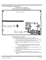
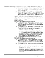
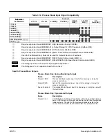
Home (Orient) Switch Input
The Home or Orient function causes the motor shaft to rotate to a predefined home
position. The homing function allows shaft rotation in the drive forward direction only.
The home position is located when a machine mounted switch or the encoder “Index”
pulse is activated (closed). Home is defined by a rising signal edge at terminal J1-27.
The shaft will continue to rotate only in a “Drive Forward” direction for a user defined
offset value. The offset is programmed in the Level 2 Miscellaneous Homing Offset
parameter. The speed at which the motor will “Home” or orient is set with the Level 2
Miscellaneous Homing Speed parameter.
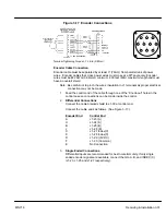
A machine mounted switch may be used to define the Home position in place of the
encoder index channel. A differential line driver output from a solid state switch is
preferred for best noise immunity. Connect this differential output to terminals J1-27 and
J1-28.
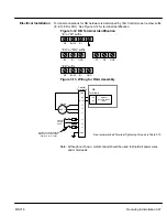
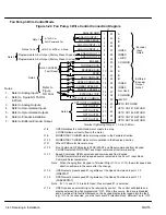
A single ended solid-state switch or limit switch should be wired as shown in Figure 3-18.
Regardless of the type of switch used, clean rising and falling edges at J1-27 are required
for accurate positioning.
Note: Control requires dynamic brake hardware for Orient (Homing) function to
work. Control will trip without dynamic brake hardware installed. Size A and B
controls ( “–E” suffix) are shipped with factory installed dynamic brake
hardware.
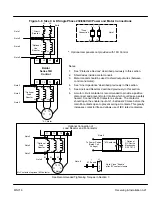
Figure 3-18 Typical Home or Orient Switch Connections
27
28
29
30
Common
+5V
INDEX
INDEX
J1
27
28
29
30
Common
+5V
INDEX
INDEX
J1
Limit Switch (Closed at HOME).
5VDC Proximity Switch
Terminal Tightening Torque = 7 Lb-in. (0.8 Nm).
+5V Input
Output
Common
Buffered Encoder Output
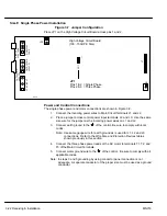
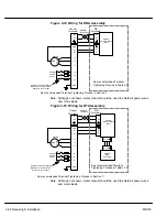
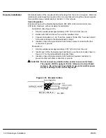
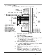
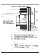
The control provides a buffered encoder output on pins J1-31 to J1-38 as shown in Figure
3-19. This output may be used by external hardware to monitor the encoder signals. It is
recommended that this output only drive one output circuit load.
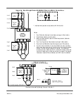
Figure 3-19 Buffered Encoder Output
30
31
32
33
34
35
36
37
38
29
COMMON
+5VDC
COMMON
A
A
B
B
INDEX
INDEX
Not Used
Buffered
Encoder
Output
26LS31
A
A
B
B
C
C
D
D
IN B
IN C
IN D
IN A
E
E
From
Processor
Terminal tightening torque is
7 lb–in (0.8 Nm) maximum.
J1
Содержание 18H Series
Страница 1: ...SERIES 18H AC Flux Vector Control Installation Operating Manual 9 97 MN718 VECTOR DRIVE ...
Страница 105: ...Section 1 General Information 5 18 Troubleshooting MN718 ...
Страница 109: ...Section 1 General Information 6 4 Manual Tuning the Series 18H Control MN718 ...
Страница 144: ...Appendix C Appendix C 1 MN718 ...


