26 |
Baker Hughes
© 2022 Baker Hughes Company. All rights reserved.
23. Lubricate the yoke studs with “Fel-Pro Nickel
Ease.” Carefully lower the yoke/spring assembly
over the spindle while aligning the yoke as shown
in Figure 17 of Section XIV. Ensuring that the
yoke vent hole is on the side of the valve opposite
the inspection port, make certain that the yoke
does not bind on the lift stop. Care should then be
taken to tighten down the yoke evenly, so as to
prevent distortion and misalignment.
24. Raise the lift stop until it contacts the yoke. Then,
lower the lift stop to achieve the proper dimension
shown in Table 8, or the restricted lift identified on
the valve nameplate.
Note:
Do not deviate from stamped nameplate lift.
The lift stop must be adjusted to the rated lift
marked on the nameplate, plus an additional
amount as indicated. The additional lift is to
compensate for the heated condition of the lower
spindle when the valve is in operation.
Note:
For all Consolidated Series 2700 Safety Valves,
one revolution of the lift stop equals .063” (1.59
mm) of lift. There are six (6) notches on the lift
stop, so each notch of adjustment represents
approximately .010” (0.25 mm) lift.
25. Secure the lift stop with a cotter pin.
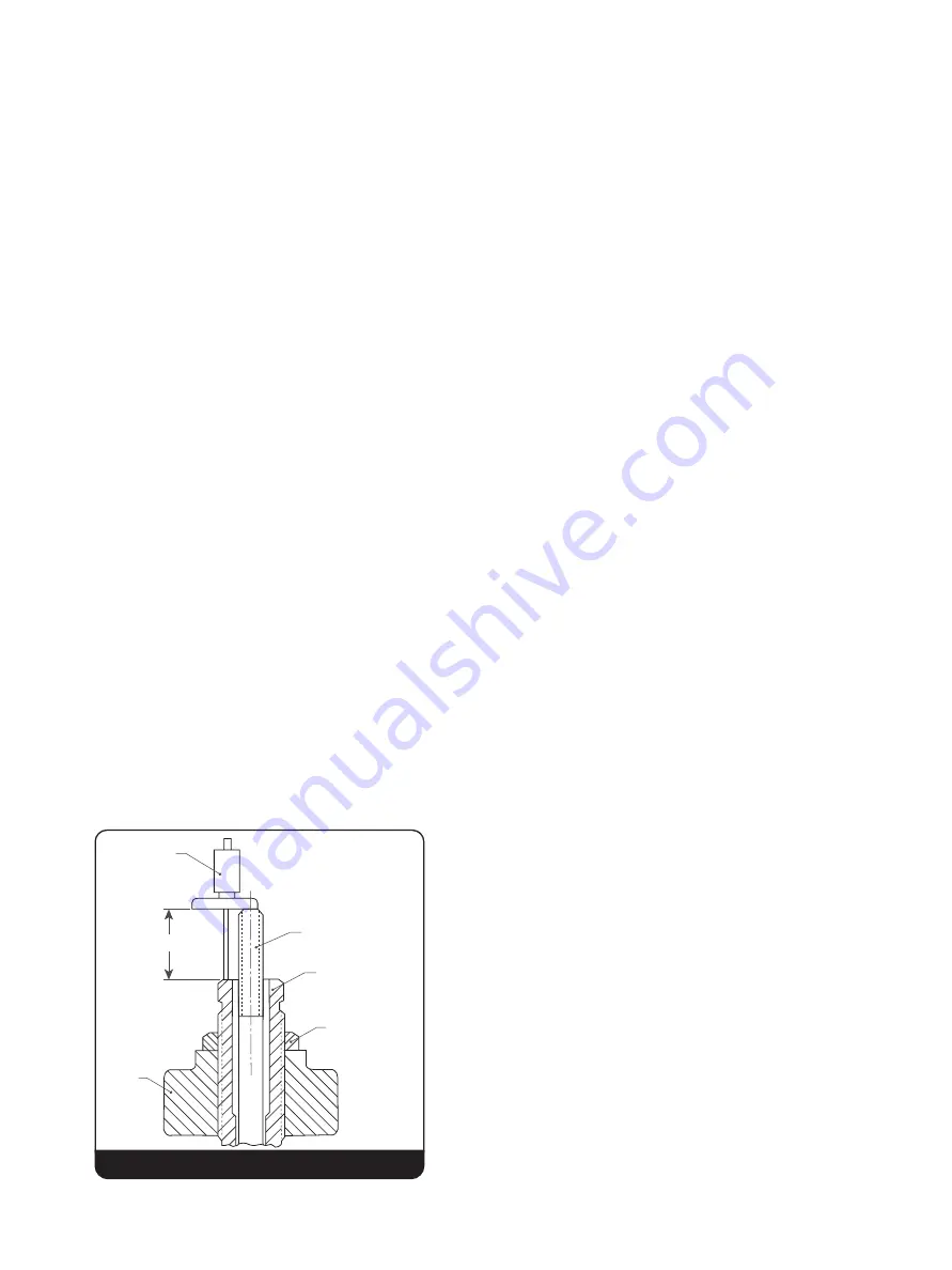
26. Refer to Figure 16 and establish Dimension A
to that previously recorded in Section XI.B.4 of
“Disassembly.”
27. Ensure that the top washer arms do not remain
in contact with the yoke, after each compression
screw adjustment.
28. The valve is now ready for testing, after which the
following steps can be taken:
a. After testing, the compression screw should be
locked firmly in place with the lock nut.
b. Install the release nut onto the spindle. Then
thread clockwise until the release nut is fully
engaged on the spindle thread and the cotter
pin hole is aligned. For numbers 1, 2, 3, and
4 orifices, run the release nut down enough
to allow the lock nut to fully engage, and then
loosely install the lock nut.
c. Install the cap over the release nut, and seat
the cap firmly into place on the yoke. Install
the top lever in the cap and then insert the top
lever pin through the top lever and cap holes.
d. Adjust the release nut, until it clears the top
lever by .125” (3.20 mm). Remove the lever
pin, top lever and cap. Next, insert a cotter pin
through the release nut slots and the spindle,
and spread the cotter pin ends. Re-assemble
the cap with the drop lever, top lever, and
top lever pin. Install a cotter pin to lock the
top lever pin in place. A final check should be
made to ensure the proper clearance exists
between the release nut and the top lever.
Finally, tighten the cap set screw to secure the
cap.
29. After testing the valve for proper set point and
blowdown, the ring pins, top lever pin and lift stop
shall be sealed. Run a continuous wire through
the sealing wire holes leaving both ends in such a
manner that a lead seal may be threaded to them.
Before crimping the seal, assure that the parts
being sealed cannot be tampered with, without
removing the seal.
DEPTH
MICROMETER
A
YOKE
SPINDLE
COMPRESSION
SCREW
COMPRESSION
SCREW LOCKNUT
Figure 16
XIV. Re-Assembly Instructions (Cont.)


