28 |
Baker Hughes
© 2022 Baker Hughes Company. All rights reserved.
3. Apply the gag load by turning the gag screw
clockwise. If the gag on any valve has not been
tightened sufficiently, the valve will leak. On steam
service the leakage is accompanied by a “sizzling”
sound.
If this occurs, the hydrostatic test pressure or steam
pressure should be reduced until the valve becomes
tight and, then, the gag should be tightened still further.
This procedure must be followed exactly, since
it is very difficult to stop the leak by additional
gagging once it has started. Any attempt to
stop the leakage through the valve, without first
lowering the system pressure, could result in
damage to the valve seats.
4. After the hydrostatic test or steam test is
completed, the gags should be removed when
the hydrostatic pressure has been reduced to 80
percent to 90 percent of the pressure of the low
set valve.
Note:
Under no circumstances should the gags
be left on the valves during normal boiler
operation.
C. Presetting Adjusting Rings
1. Remove the caps on all valves to be set on the
steam drum and main steam line.
2. Install a currently calibrated pressure gauge on
the drum near the valve being set. When the main
steam valve is to be set, install the calibrated
gauge upstream from the valves on the main
steam line to read line pressure.
3. After the pressure in the boiler has increased to
80 percent of operating pressure, install gags on
all boiler valves not being tested. Gags should be
installed hand tight (no wrenches or mechanical
force).
4. On the valve to be tested, use the following
procedure and Table 9, to bring the adjusting ring
to seat level.
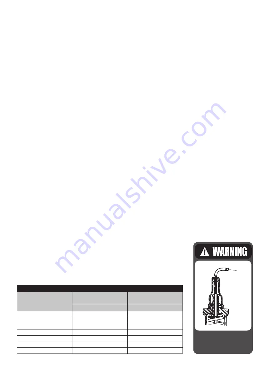
a) Gag the valve to prevent the disc from
accidentally lifting from the seat during
adjustment.
b) Remove both service port plugs.
c) Remove the upper ring pin.
d) Move the upper ring until it is level with the
disc holder.
e) From this point, move the upper adjusting
ring down (from right to left as viewed through
the service plug hole), counting the number
of notches until the number in Column “B”
in Table 9 appropriate to the orifice size is
reached. This will establish the upper adjusting
ring at seat level.
f) Adjust the upper adjusting ring as indicated in
the upper ring column of Table 10, using either
the Saturated Column or Superheated Column
as conditions warrant
g) Replace the ring pin in the valve to hold
the upper adjusting ring in position without
binding.
h) Remove the lower ring pin.
i) Move the lower adjusting ring up until it
contacts the disc holder.
j) After referring to Table 9, lower the adjusting
ring the number of notches indicated in
Column “A”
This setting will
place the lower
adjusting ring at
seat level.
XV. Setting and Testing (Cont.)
Table 9: Adjusting Ring Seat Level
Orifice
Lower Ring Seat Level
Adjustment in Notches
Upper Ring Seat Level
Adjustment in Notches
(Column A)
(Column B)
1
7
10
2
8
12
3
12
16
5
12
16
4
12
16
6
30
45
7Q
30
45
Gag safety valve during
ring adjustments to avoid
possible severe personal
injury or death.
GAG


