22 |
Baker Hughes
© 2022 Baker Hughes Company. All rights reserved.
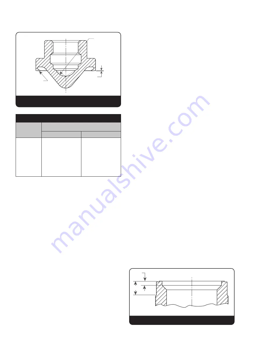
(ii) The Thermodisc cannot be machined. If,
after lapping, Dimension M, in Figure 14,
does not meet the minimum specified in
Table 5, the disc should be replaced.
iii) It may not be necessary to use all the laps
at any one time, but having a sufficient
supply on hand will save reconditioning
time. The laps should be reconditioned
on a flat lapping plate. A lap should not
be used on more than one valve without
being reconditioned. Laps must be
checked for flatness prior to use, and
at frequent intervals during use. A lap
that is flat within one-half light band is
considered satisfactory. Information on
the Monochromatic Light and optical flat is
available, upon request, from Baker Hughes
Consolidated Field Service Department.
(iv) To recondition a ring lap, wipe all compound
from the lapping plate and ring lap, then
move the ring lap in a figure-eight motion
on a lapping plate. If the lap is not flat, a
shadow will be apparent. To remove the
shadow, coat the lapping plate with 1000-
grit compound and lap the ring with figure-
eight motions covering the lapping plate.
10. Seat Bushing
a. A Consolidated reseating machine should
be used to recondition badly worn and out
of tolerance bushing seats. This machine
can be provided by Consolidated’s Service
Department, and eliminates the need to
remove a valve from the unit. The machine
is mounted in place of the yoke and cuts the
top face, inside diameter, and outside of the
bushing, to establish the correct height, angles,
and diameters.
b. The use of a reseating machine is suggested
for reconditioning badly worn seats, or for
re-establishing Dimension E per Figure 15.
Dimension E should be re-established when it is
less than .010” (0.25 mm) for orifices 1, 2, 3, 5
and 4; and less than .030” (0.76 mm) for orifices
6 and Q.
c. To lap the bushing seat.
Note: If the bushing seat surface requires
extensive lapping or reconditioning, a
reseating machine should be used prior to
lapping.
(i) Cover the seat lap face with a light coating
of 1-A Clover Compound and gently place
the lap on the valve bushing seat.
Note: A heavy coat of lapping compound tends to
round off the edges of the seat.
Table 5: Minimum Seat Relief
Orifice
M min.
in.
mm
#1
.004
0.10
#2
.005
0.13
#3
.006
0.15
#5
.007
0.18
#4
.008
0.20
#6
.010
0.25
#Q
.012
0.30
BEARING
SURFACE X
SURFACE L
M min.
Figure 14: Disc
XIII. Inspection and Part Replacement (Cont.)
E
D
Figure 15


