20 |
Baker Hughes
© 2022 Baker Hughes Company. All rights reserved.
XIII. Inspection and Part Replacement (Cont.)
DISC
RING LAP
FLAT
SURFACE
SPINDLE
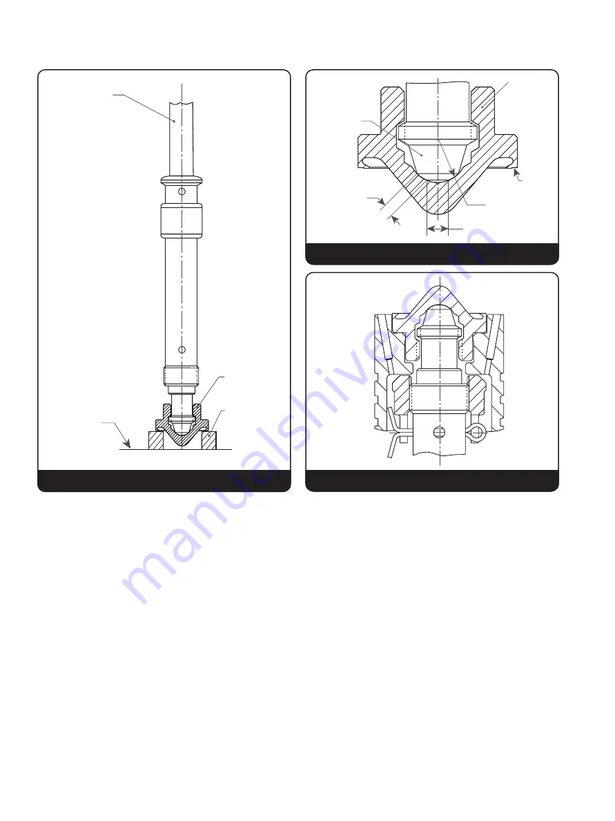
Figure 11: Spindle Tip and Disc “Pocket”
DISC
R
SEAT
STEP
SPINDLE
NOSE
BEARING
BAND WIDTH
FLAT DIAMETER
Figure 12: Disc to Spindle Lapping
Figure 13
b. To straighten the spindle, place the unthreaded
portion of the small and large end in padded
V blocks, with the point of maximum indicator
readout upward, and then apply a downward
force with a padded press or jack as required,
until the spindle is within the specifications.
c. Other parts of the spindle not used as working
surfaces may run out considerably more
than .007” (0.18 mm), but this should not be
regarded as unacceptable. Although the upper
thread end is not a working surface, excessive
bending in this area could affect the accuracy
of the Consolidated Hydroset Test Device or
EVT software, if either of these devices is used
to verify valve set pressure.
d. Apply a small amount of lapping compound
(1A) on the tip of the spindle. Install the disc—
without the disc holder - onto the spindle tip,
turning it clockwise until the disc threads drop
out. Place a ring lap on a table, or similar
flat surface, and wipe the exposed surface
of the lap clean. Insert the disc nose into a
ring lap, so that the seat contacts the lap
surface. Oscillate the spindle using 360-degree
oscillations for approximately 15 seconds,
then check the spindle tip and disc “pocket” to
determine progress. (See Figure 11.)
e. The spindle nose should be ground into the
disc pocket until the bearing is clearly marked.
The band position is shown in Figure 12.
f. Place the disc holder on the spindle, allowing
it to rest on the face of the disc collar as
previously shown in Figure 7 on Section XI.B.
Then assemble the disc holder and new disc.
The disc should be free enough to rock on the
spindle tip. If there is no freedom, lower the
disc collar until the disc is free to rock slightly
initially, approximately .001 to .002” (0.25 to


