4. CONFIGURATION
In this example there is more equipment connected behind the router, using a Switch.
Every device connected behind the router has its own IP address and this is the address to fill
in the
Server IP Address
field in the NAT configuration. These devices are all communicating
on the port 80, but you can set the Port Forwarding in the NAT configuration – see Figure 31
–
Public Port
and
Private Port
fields. It is now configured to access 192.168.1.2:80 socket
behind the router when accessing 10.0.0.1:81 from the Internet and so on. If you send the
ping request to the public IP address of the router (10.0.0.1), the router will respond as usual
(not forwarding). If you access the IP address 10.0.0.1 in the browser (it is port 80), nothing
will happen – there is neither 80 port in Public Port list defined nor you have checked the
Enable remote HTTP access on port 80
. And since the
Send all remaining incoming packets
to default server
is not enabled, the attempt of connection will lead to failure.
4.9
OpenVPN Tunnel Configuration
OpenVPN tunnel configuration can be called up by option
OpenVPN
item in the menu.
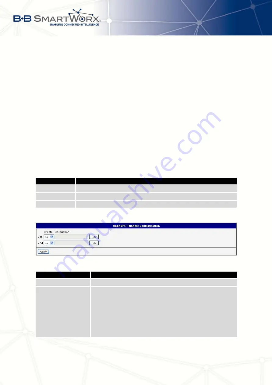
OpenVPN tunnel allows protected connection of two networks LAN to the one which looks like
one homogenous. In the
OpenVPN Tunnels Configuration
window are two rows, each row for
one configured OpenVPN tunnel.
Item
Description
Create
Enables the individual tunnels
Description
Displays a name of the tunnel specified in the configuration form
Edit
Configuration of OpenVPN tunnel
Table 33: Overview OpenVPN tunnels
Figure 32: OpenVPN tunnels configuration
Item
Description
Description
Description (or name) of tunnel
Protocol
Communication protocol:
•
UDP
– OpenVPN will communicate using UDP
•
TCP server
– OpenVPN will communicate using TCP in
server mode
•
TCP client
– OpenVPN will communicate using TCP in
client mode
Continued on next page
46
Содержание V3
Страница 1: ...Configuration Manual for v3 Routers ...
Страница 17: ...3 STATUS Figure 2 Mobile WAN status 8 ...
Страница 20: ...3 STATUS Figure 4 WiFi Scan 11 ...
Страница 29: ...4 CONFIGURATION Figure 11 Example 1 Topology of LAN Configuration Figure 12 Example 1 LAN Configuration 20 ...
Страница 37: ...4 CONFIGURATION Figure 17 Mobile WAN configuration 28 ...
Страница 64: ...4 CONFIGURATION Figure 36 IPsec tunnels configuration 55 ...
Страница 76: ...4 CONFIGURATION Figure 47 Example of the MIB browser Figure 48 Example of SNMP configuration 67 ...
Страница 91: ...4 CONFIGURATION Figure 59 Example 2 USB port configuration 82 ...


