


Chapter
D
: Emission Control Systems Diagnosis and Repair
82
If you find liquid gasoline in the canister, follow the pro-
cedure in the Service Manual to remove and replace the
canister.
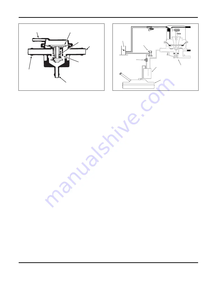
Leak Detection Pump (LDP) Systems
The Leak Detection Pump must perform two primary
functions:
• Pressurize the EVAP system
• Seal the charcoal canister
The LDP system, figure 4-16, contains the following
components:
• Three-port solenoid that activates the two primary
functions of the system
• Vacuum-driven pump that contains a reed switch,
check valves, and a spring loaded diaphragm
• Canister vent valve that contains a spring loaded
vent seal valve
When the outside ambient air temperature is within pre-
determined parameters, the leak detection portion of the
monitor is run immediately after a cold start. The three-
port solenoid is energized, allowing vacuum to pull the
pump diaphragm up. This draws air from the atmosphere
into the pump. When the solenoid is deenergized, the
pump is sealed, spring pressure drives the diaphragm
down, and air is pumped into the system. Insight: In
order for the monitor to run, the fuel tank must be 15%-
85% full. If the tank is too empty or too full, the LDP will
not run.
The solenoid and diagram pump cycles to pressurize the
EVAP system. The spring on the diaphragm is calibrat-
ed to 7.5 inches of water. If no leaks are present, pres-
sure equalizes and the pump cycle rate falls to zero.
Insight: If a DTC is present, check the fuel filler cap. A
primary cause of an LDP failure is a loose or incorrect
fuel filler cap.
Non-LDP Systems
On a vehicle without an EVAP leak detection pump sys-
tem, changes in short term memory and movement in
target IAC at idle or idle speed change, are used to mon-
itor the system. There are two steps for this test.
Step One
Step one is a non-intrusive test. The PCM compares
adaptive memory values between purge and purgefree
cells. The PCM uses these values to determine the
amount of fuel vapors entering the system. If the differ-
ences between the cells exceeds a predetermined
value, the test passes. If not, then the monitor advances
to stage two.
Step Two
Once the enabling conditions are met, the PCM de-en-
ergizes the canister purge solenoid. The PCM then waits
until engine RPM and idle air control have stabilized.
Once stable, the PCM increments the purge solenoid
cycle rate approximately 6% every eight engine revolu-
tions. If during the test any one of three conditions occur
before the purge solenoid cycle reaches 100%, the
EVAP system is considered to be operational and the
test passes. These conditions are as follows:
• RPM rises by a predetermined amount
• Short term drops by a predetermined amount
• Idle air control closes by a predetermined amount
When neither of the previous conditions occur, the test
fails and the PCM will store a DTC for the failure.
Canister Filter Replacement
A few older vehicles had provisions for servicing the fil-
ter in the canister. Late-model vehicles do not require
maintenance of the charcoal canister.
MANIFOLD
VACUUM
DIAPHRAGM
SPRING
CANISTER
VALVE SEAT
CARBURETOR
BOWL
PURGE
VACUUM
Fig. 4-15.
A simple vacuum-activated canister purge valve for a
carburetor equipped engine.
LEAK DETECTION
PUMP
FUEL TANK
CANISTER
PURGE
SOLENOID
TEST
PORT
THROTTLE
BODY
Fig. 4-16.
Typical EVAP system equipped with a leak detection
pump.
Содержание ASE-A8
Страница 2: ......