


Chapter
E
: Computerized Engine Control Diagnosis And Repair (Including OBD II)
106
nal at a 50 percent duty cycle, the voltage would read
2.5 volts.
For automotive applications, when dealing with digital
waves, and especially with ECM outputs, we are con-
cerned with the amount of time the signal is low, rather
then high. This is because the low time is when the dri-
ving transistor is on, completing the circuit to ground.
You can measure duty cycle with a DVOM that has a
duty cycle setting. Attach the red lead to the signal wire
and the black lead to a good engine ground, figure 5-30.
PCM Pin Voltage Charts
A PCM pin voltage chart, figure 5-31, identifies all the
connector terminals at the main harness connector by
number, circuit name, and the voltage levels that should
be present under various conditions. Some circuits have
different voltage specifications with the key on and the
engine off, during cranking, and when the engine is run-
ning. Use the pin voltage charts to check input signals
to the PCM and output signals from the PCM. Checking
signals at the PCM harness connector is closely related
to sensor operating range tests.
Check Ground Continuity
Use a DMM to check the voltage drop across the main
PCM ground connection, figure 5-26. Also, check volt-
age drop across the ground connection of any sensor
that may be causing the problem. Refer to the Service
Manual for the correct pin locations to conduct the
tests. Low resistance ground connections are critical for
electronic control circuits.
With the ignition on, voltage drop across the ground
connection for an electronic circuit should be 0.1 volt or
less. The voltage drop across a high resistance ground
connection in series with a sensor circuit increases the
signal voltage of the sensor. This ground resistance can
offset the signal voltage enough to cause serious drive-
ability problems. For example, on a throttle position
sensor that operates on a 5 volt reference, a 0.5 volt
drop across the ground connection equals a 10-percent
error in throttle angle measurement.
Troubleshooting Intermittent Problems
Intermittent driveability problems can often be the ex-
tremely difficult to diagnose and repair. A soft code in
memory provides a clue as to the general area in which
to start testing. Remember, however, that if a soft code
is erased, the problem that set it may not recur right
away. To reset a soft code, simulate the conditions that
cause the problem during a road test to catch the inter-
mittent fault. The following paragraphs outline some
basic points that can help troubleshoot intermittent
problems.
Diagnostic Tools
Intermittent problems require the use of various tools to
pinpoint the actual cause. Both the DMM and the scan
tool are valuable in most cases however occasionally
the need for more enhanced signal information may be
required. For these instances the use of a DSO may be
necessary. The DSO allows the technician to view volt-
age signals over time while storing the information for
later retrieval and review. Most oscilloscopes in use
today in the automotive market are of the DSO design.
Simulate the Problem
Try to recreate the conditions that the customer de-
scribes. It may not always be possible to duplicate the
conditions exactly. Generally, driving condition de-
scribed by the customer can be recreated during a road
test. For cold starting problems, the vehicle may have to
stand overnight to recreate the conditions. If the prob-
lem caused a soft code, try to get the code to reoccur
during testing.
Wiggle Tests and Output Cycling Tests
Most control systems have long term memory that
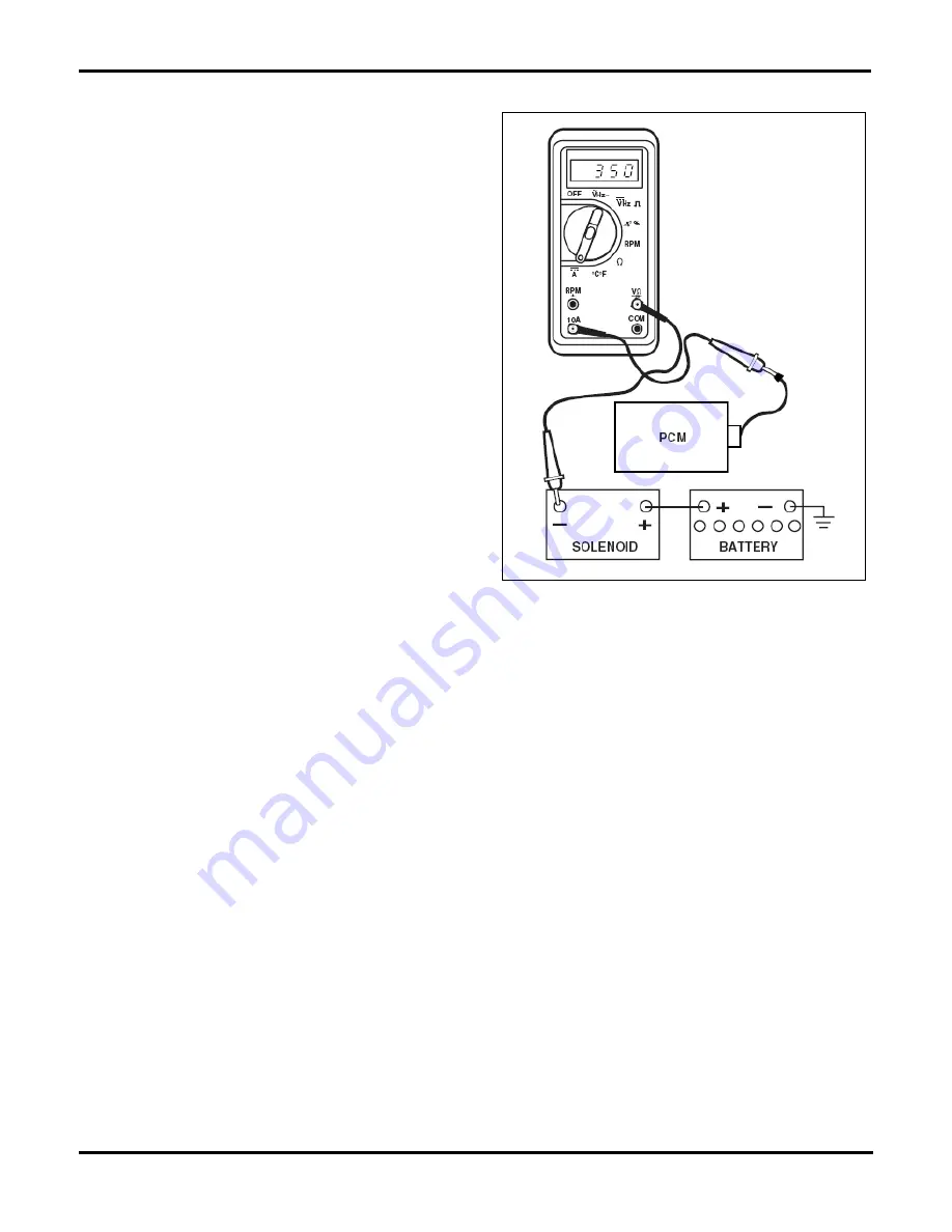
Fig. 5-27
. Checking amperage draw through a solenoid driver circuit.
Содержание ASE-A8
Страница 2: ......