


Chapter
B
: Ignition System Diagnosis and Repair
48
When a slot in the trigger wheel is aligned with the
sensor the signal is low because the magnetic filed is
not engulfing the Hall element.
When a slot in the trigger wheel is not aligned with the
element, the magnetic field saturates the Hall element
causing it to switch on and conduct current. Each time
a slot passes the sensor, the signal generated by the
Hall element changes state. Depending upon the appli-
cation, this signal may be amplified or inverted before it
is transmitted to the PCM. Therefore, there is no estab-
lished rule as to whether the signal is high or low with
respect to the strength of the magnetic field.
When examining a scope trace, look for sharp, clean
state change transitions and a signal that pulls to
ground. Amplitude should be even for all waveforms,
the pattern should be consistent, and peaks should be
at the specified voltage level. The shape and position of
the slots on the shutter wheel determine the shape and
duty cycle of the waveform. Some Hall-effect sensor
patterns have a slight rounding at the top corners of the
trace that can generally be overlooked. Remember, the
PCM looks for switching at the midpoint of the voltage
range, not at the top or bottom. However, rounding at
the bottom corners of the trace should sound an alarm.
This is often caused by high-resistance on the ground
circuit, often from a poor connection, making it difficult
for the signal to completely ground. Also, check for the
correct voltage on the power circuit to the Hall element.
A problem here can cause problems on the signal cir-
cuit.
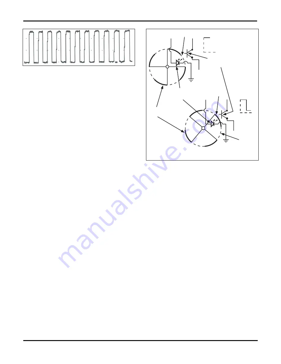
Optical Sensor
An optical sensor uses a light-emitting diode (LED), a
shutter wheel, and a phototransistor to produce a digi-
tal signal that changes frequency in proportion to rota-
tional speed, figure 2-26. Like a Hall-effect sensor, an
optical sensor requires an external power source and
uses a three-wire circuit. One wire carries power to op-
erate the LED, one is the signal generated by the tran-
sistor, and the third provides a common ground path.
Signal voltage, which is usually 5 volts, switches on and
off as the rotating shutter passes between the photo-
transistor and LED to toggle the ground circuit. When
the shutter allows light to shine on the phototransistor,
the base of the transistor switches, causing the signal
voltage to change state. When the reflector plate blocks
the light to the phototransistor, the base of the transis-
tor switches again, and signal voltage changes as well.
Optical sensors are more expensive to manufacture and
more delicate than a magnetic pickup or Hall-effect
sensor. Therefore, they are the least common of the
three types. Typically, optical sensors are used as vehi-
cle speed sensors and engine speed sensors because
their high-speed data rate is more accurate than other
sensor designs for high RPM applications. When
viewed on an oscilloscope, the waveforms will be simi-
lar to those produced by a Hall-effect sensor.
Control System Power Flow
In discussing power flow through the electronic control
system we will use the composite vehicle as an exam-
ple. Although this is a basic and simplified system, the
principles that apply here also apply to most automotive
control systems. The only major differences between
most systems are the number of controlled circuits, the
design characteristics of individual components, and
the arrangement of PCM terminal connections, or pins,
figure 2-27 and 2-28.
Fig. 2-25.
Square-wave pattern from a Hall-effect sensor.
PHOTO
TRANSISTOR
SHUTTER
WHEEL
LIGHT-EMITTING
DIODE (LED)
HIGH
SIGNAL
VOLTAGE
SIGNAL
VOLTAGE
VANE
WINDOW
WINDOW
LOW
Fig. 2-26.
An optical sensor uses an LED and a light-sensitive
transistor to transmit a digital square waveform to the PCM at a
variable frequency.
Содержание ASE-A8
Страница 2: ......