Autoscope Image Sensing IntelliSight Скачать руководство пользователя страница 71

Chapter 5:

Configuring IntelliSight Devices

Autoscope IntelliSight User Guide

©2022 Image Sensing Systems Inc.

5-32

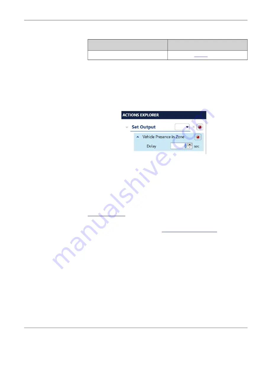
5. Do you want to delay the activation of a Vehicle Presence condition?

One use of this function is for right turn zones that share an output with a 

through zone. For example, a right turn lane could have a delay in case a car 

that is making a right turn can turn right away and does not need to wait for a 

green light. If there is not a car waiting in the through lane, and the right-

turning vehicle clears the zone before the delay, there is no call to the 

controller.

6. Click the drop-down indicator to the left of Vehicle Presence.

7. Select or enter the number of seconds to delay.
8. To collapse the options box, click the arrow to the left of Vehicle Presence.
9. When all conditions and actions have been defined, click 

A

PPLY

 C

HANGES

.

All assigned outputs are set to “call” (ON), and stay in “call” until detection 

sets the output OFF or for a maximum of five minutes, whichever occurs 

first. 
To change the initial state of the output or to set the output options, use the 

“Actions Explorer”

.

NOTE:  

After all zones are defined and configured, it is recommended that the 

configuration be archived (se

“Save Archive” on page 6

-

6

).

Yes

No

Continue with the next step.

Proceed to 

Step 9

.

Содержание Image Sensing IntelliSight

Страница 1: ...Autoscope IntelliSight User Guide 2022 Image Sensing Systems Inc A700 7131 Rev B...

Страница 2: ...trademark of Image Sensing Systems Inc registered in the United States and other countries Autoscope IntelliSight is a trademark of Image Sensing Systems Inc All other product names referenced in this...

Страница 3: ...1 6 Ethernet Port LEDs 1 6 IntelliSight Processor Status LED 1 6 Autoscope I O Module 1 7 LEDs 1 8 Connectors 1 9 Jumper Pins 1 10 Rear Connector 1 11 Supervisor Software 1 13 Accessing Online Help 1...

Страница 4: ...resence Zone 5 12 Add Zones From Calibration 5 13 Add Zones Manually 5 15 Adding an Advance Presence Zone 5 20 Adding Receding Traffic Zones 5 22 Adding a Pedestrian Crosswalk Zone 5 24 Adding a Pedes...

Страница 5: ...Network 6 12 Outputs Phases Failsafe and All Call For IntelliSight Devices 6 12 Assigning Outputs 6 12 Failsafe Operations 6 13 Port Forwarding 6 15 Restart Device 6 15 Set Time 6 16 Streaming Video F...

Страница 6: ...n three decades of proven above ground video detection experience Autoscope IntelliSight delivers the highest levels of innovation and performance in an easy to use detection solution that supports a...

Страница 7: ...om the power supply is connected This provides the power required for the IntelliSight Processor and connected IntelliSight Cameras to operate This can be screwed in to prevent from disconnection or r...

Страница 8: ...applied to the IntelliSight Processor 3 System Status LED Used for diagnostic and status purposes see Status LED on page 1 6 4 HDMI Port reserved for future use 5 Two standard USB ports Currently use...

Страница 9: ...IntelliSight Camera Table 1 3 IntelliSight Camera Specifications Item Description Electrical Power PoE to cameras via provided switch Environmental Temperature range 40 C to 60 C 40 F to 140 F Humidi...

Страница 10: ...type of address is defined through the Supervisor For information on defining the IP address see Add Device by IP on page 6 5 I O Port The I O port is used to communicate to the Autoscope I O card wh...

Страница 11: ...ernet Port LEDs There are two LEDs associated with each RJ 45 port items 6 7 8 9 and 10 in Table 1 2 on page 1 3 which indicate the speed of the network connection and activity as follows Left LED 100...

Страница 12: ...O Module The Autoscope I O Module is an optional card that converts detection data from the IntelliSight Processor to standard wired inputs and outputs in the traffic cabinet The Module is shown in F...

Страница 13: ...ntelliSight Processor are OK Not lit The I O Module is powered off Table 1 4 Autoscope I O Module Specifications Item Description Electrical Power input 12 VDC min 50 VDC max Current draw 500ma maximu...

Страница 14: ...Output 22 Output 35 5 Output 4 Output 55 27 Output 23 Output 36 6 Output 5 Output 56 28 Output 24 Output 37 7 Output 6 Output 57 29 Input 1 Output 38 8 Output 7 Output 58 30 Input 2 Output 50 9 Output...

Страница 15: ...r Pin Locations Table 1 6 Jumper Chart Default Settings Jumper Jumper Across Pins 1 2 Jumper Across Pins 2 3 Factory Default JP1 Output Failsafe Enable Output Failsafe Disable 1 2 JP2 Power Loss Fails...

Страница 16: ...utput 38 NC 3 Input 2 Output 37 NC 4 Input 3 Output 36 NC 5 Input 4 Output 35 NC 6 Input 5 Output 34 Output 64 7 Input 6 Output 33 Output 63 8 Input 7 Output 32 Output 62 9 Input 8 Output 31 Output 61...

Страница 17: ...put 18 Output 48 23 NC Output 17 Output 47 24 Output 8 Output 16 Output 46 25 Output 7 Output 15 Output 45 26 Output 6 Output 14 Output 44 27 Output 5 Output 13 Output 43 28 Output 4 Output 12 Output...

Страница 18: ...o access the help system press F1 on the keyboard A separate window appears with the help page for the screen currently being displayed in the Supervisor Various tabs provide for locating and displayi...

Страница 19: ...rs when it determines it is not able to perform detection or when the zoom setting for the camera is changed Output the signal sent to the Controller when the condition is met Recall what occurs when...

Страница 20: ...per Tie wraps for cable strain relief Radios or cell phones to communicate between the cabinet and the bucket truck Computer and Ethernet network cable Faceplate cleaning supplies lint free lens tissu...

Страница 21: ...ends with Rj 45 connectors NOTE A maximum of four IntelliSight Cameras can be connected to the IntelliSight Processor Use the following guidelines to install the Ethernet cable between the IntelliSig...

Страница 22: ...Placement The camera should be located horizontally on the mast arm or luminaire arm in a level position and aimed towards approaching traffic The actual alignment will depend on the number of lanes a...

Страница 23: ...nt along the desired lane line is not possible shift to the nearest lane line towards the center of the field of view Two or Three Lanes Four Lanes with Left Turn Aim here Thru lane 2 or 3 Thru lane 1...

Страница 24: ...ttings during the aiming procedure For example in Figure 2 5 and Figure 2 6 the camera Cam is set to detect southbound traffic The solid green line represents where the camera should be aligned when i...

Страница 25: ...Chapter 2 Pre Installation Considerations Autoscope IntelliSight User Guide 2022 Image Sensing Systems Inc 2 6 Figure 2 6 Alternative field of view N S W E Cam...

Страница 26: ...n this sequence the IntelliSight Cameras are installed followed by the IntelliSight Processor and then if required the IntelliSight I O Module Warning Hazard of damage to personnel and system componen...

Страница 27: ...power supply to the IntelliSight Processor and the PoE switch The power supply will have V1 and V2 connections Connect the red wire to V and the black wire to V1 on the power supply Then connect the r...

Страница 28: ...ocessor and the PoE switch If desired a circuit breaker can be installed before the connection to the power supply 6 Connect a laptop to the maintenance port of the Processor before moving on to Camer...

Страница 29: ...How to remove external sunshade 2 If using an external mount or conduit fixing hole and banding directly to pole or mast arm feed the network cable through the access hole If banding to the pole feed...

Страница 30: ...5 connector on the end of the Cat5e or Cat6 cable Use the RJ45 cap to feed the cable through the included grommet Then slightly pull it back to seal it properly 4 Install the adapter box mounting pin...

Страница 31: ...the camera and level it Then tighten the screws until they are snug enough that the camera does not move See Field of View FOV on page 2 5 for guidance 8 Connect the camera to the POE switch in the ca...

Страница 32: ...rs include Microsoft Edge IE mode Microsoft Edge Chrome Firefox and Internet Explorer 12 Click on the three dots then click Download 13 Access the downloads folder on your laptop and open the EasyIpSe...

Страница 33: ...ork Settings then press Static NOTE If cameras have been powered on for over 20 minutes they will need to be rebooted 18 Do this for each camera 19 Locate the IP address NOTE Make a note of the IP add...

Страница 34: ...UI NOTE Do not change any other settings Press Set then Close Click the Live tab and leave open while finishing the camera install 22 Tighten the Pan tilt and yaw the screws to the specified amount i...

Страница 35: ...ator rights on the computer in order to install the Supervisor Installing the Software To install the software do the following 1 Locate and double click the file ISSSupervisorSetup_vx x x x exe where...

Страница 36: ...u want the files installed in the default location 5 Click Next The following appears Yes No Continue with the next step 1 Click Browse 2 Select the new location 3 Verify the new location appears in t...

Страница 37: ...Chapter 4 Software Installation Autoscope IntelliSight User Guide 2022 Image Sensing Systems Inc 4 3 6 Click Next...

Страница 38: ...pe IntelliSight User Guide 2022 Image Sensing Systems Inc 4 4 The following appears NOTE If the Visual C Redistributable dependency is not on the computer it will be installed automatically 7 Click In...

Страница 39: ...ntelliSight User Guide 2022 Image Sensing Systems Inc 4 5 8 To start the Supervisor automatically after the install is complete select the check box 9 Click Finish to complete the install A shortcut f...

Страница 40: ...Supervisor To start the Supervisor software do the following 1 Connect the computer to the IntelliSight Processor using one of the following methods Ethernet cable Plug one end of a CAT5 CAT5e or CAT6...

Страница 41: ...e list If devices do not appear in the list click LEARN NETWORK If IntelliSight Processors are connected through a routed network it may be necessary to enter the IP address of the IntelliSight Proces...

Страница 42: ...click Program Settings NOTE At present English is the only supported language 2 Select the measurement units for distances English translates all distance measurements into feet Metric translates all...

Страница 43: ...Processor to be configured The following appears An image of all setup cameras will appear if the cameras are connected and online one in each of the four quadrants of the image area The order of app...

Страница 44: ...the IntelliSight Processor s clock is set by TS2 time set commands from a TS2 compatible controller The IntelliSight Processor monitors the TS2 time every minute and if the difference between the two...

Страница 45: ...WAN network interface Primary DNS Address of the primary DNS server Only available for the WAN interface and when Enable DHCP is not selected Secondary DNS Address of the secondary DNS server Only ava...

Страница 46: ...lished Configure the device settings Use the camera UI to adjust the zoom and focus if needed Calibrate the camera Add zones stopline advance Assign conditions actions and optionally video overlays to...

Страница 47: ...ms Inc 5 8 The following appears 3 In the User Descriptions section enter descriptions for each field as needed The description entered for the first field is what appears as the Device Name in the ot...

Страница 48: ...a This can be found by using a third party tool The RSTP Port should be 554 unless specifically changed by the user The RSTP Presentation defines the channel and stream you are trying to connect to Fo...

Страница 49: ...e following appears 2 Move the cursor to one of the corner or lane markers then click and drag to the desired location NOTE It is important that the calibration overlay has parallel lines This would n...

Страница 50: ...the distance measurements as required by clicking on a value and typing a new one 7 Align the vertical bars with a vertical structure in the image such as a post a pole or the edge of a building If p...

Страница 51: ...lapping zones in a configuration is not recommended as this can cause poor detection performance Adding or editing a zone while playing video may cause these operations to appear delayed or jerky Data...

Страница 52: ...bration Right Turn Lane two zones appear one for a right turn lane and one covering the remainder of the lanes defined in the calibration Left and Right Turn Lanes two or three zones appear one for a...

Страница 53: ...default the vehicle presence condition is selected for each zone In addition green is selected for the zone display color when a vehicle is detected and gray when no vehicle is present in the zone Th...

Страница 54: ...apter 5 Configuring IntelliSight Devices Autoscope IntelliSight User Guide 2022 Image Sensing Systems Inc 5 15 Add Zones Manually 1 On the Device screen for the camera click ZONE SETUP 2 Click ADD ZON...

Страница 55: ...Inc 5 16 3 Move the cursor to one of the corner markers then click and drag to the desired location The arrows at the corners of the zone can be used to rotate the zone 4 Repeat for each corner until...

Страница 56: ...added to the configuration NOTE Because the original zone is probably not a perfect square or rectangle the distance measurement shown for the new zone will be different from the original 7 Adjust the...

Страница 57: ...a vehicle is detected and gray when no vehicle is present in the zone There is no default output assigned For each selected condition vehicle and bicycle presence an output must be assigned unless th...

Страница 58: ...zone 14 Do you want to add a pedestrian crosswalk zone 15 Do you want to add a pedestrian waiting zone Yes No See Adding an Advance Presence Zone on page 5 20 Continue with the next step Yes No See A...

Страница 59: ...operation to appear delayed or jerky 1 On the Zone Setup screen select the Stop Line Zone from which the Advance Zone is to be created Note the width of the Advance Zone will mimic the Stop Line Zone...

Страница 60: ...the vehicle presence condition is selected for each zone In addition green is selected for the zone display color when a vehicle is detected and gray when no vehicle is present in the zone There is no...

Страница 61: ...er objects should not be in the part of the zone where vehicles would be exiting Receding zones are ideally placed where there is maximum visual separation between vehicles which is usually as close t...

Страница 62: ...nd video overlays as required see page 5 26 NOTES By default the vehicle presence condition is selected for each zone In addition green is selected for the zone display color when a vehicle is detecte...

Страница 63: ...or to one of the corner markers then click and drag to the desired location 3 Repeat for each corner until the zone covers the crosswalk area 4 To set conditions and actions using Easy Setup see Easy...

Страница 64: ...pedestrians are waiting to cross an intersection NOTE Up to two waiting zones can be added 1 On the Zone Setup screen click Add Waiting Zone 2 Move the cursor to one of the corner markers then click a...

Страница 65: ...s When selected a bicycle icon appears at the front of zone This condition can be selected in either the Easy Setup or Zones Explorer sections Crossing Pedestrian provides a means of sending an output...

Страница 66: ...s check box is used to display overlays on the Zone Setup screen for both static images and video The types of overlays that can be added to a video image are Zone Outline this overlay shows the lines...

Страница 67: ...stead of Easy Setup To set conditions and actions using Easy Setup do the following 1 Select a zone either in the image or by clicking the zone description in the Easy Setup section NOTE A presence co...

Страница 68: ...plorer section must be used instead of Easy Setup Multiple outputs for a single condition do not appear on the Easy Setup screen To change the initial state of the output or to set the output options...

Страница 69: ...n a Crosswalk Zone Assign more than one Set Output action to a single condition Remove Set Output actions from a condition Remove the Display Zone action from a condition Assigning Vehicle or Bicycle...

Страница 70: ...for the condition This action is used to define what color the zone is to be outlined in on the video when the presence condition is detected Note it is recommended that red not be used as this is th...

Страница 71: ...e delay there is no call to the controller 6 Click the drop down indicator to the left of Vehicle Presence 7 Select or enter the number of seconds to delay 8 To collapse the options box click the arro...

Страница 72: ...ical use would be in an Advance zone to determine whether the green phase should be extended NOTE A single zone covering multiple lanes is not recommended when using Pulse outputs 1 In the Zones Explo...

Страница 73: ...walk zone has been added in the Zones Explorer section click the plus sign to the right of the zone description and select Pedestrian Crossing Rule 2 Click the drop down menu to define where a pedestr...

Страница 74: ...sence Rule The Pedestrian Presence Rule is used to detect when a pedestrian is present in the crosswalk 1 In the Zones Explorer section click the plus sign to the right of the zone description and sel...

Страница 75: ...stems Inc 5 36 3 Select or enter the number of seconds to delay The value can be between 0 and 120 seconds Default is 0 4 In the Set Output field select the output that will be sent to the controller...

Страница 76: ...and or presence conditions on the video The LED indicator associated with the overlay will light up when the output or condition is activated To use the Actions Explorer do the following 1 Click the A...

Страница 77: ...two or more vehicle presence zones share an output see Step 3 To change the pulse width for Pulse conditions see Step 7 3 Do you want to delay the activation of a Vehicle Presence condition 4 Click th...

Страница 78: ...lay text will appear on the static image 14 To change the text and appearance of the overlay click on it 15 If any changes are made click APPLY CHANGES Item Description 1 Highlight the text and type w...

Страница 79: ...ng Systems Inc 5 40 All assigned outputs are set to call ON and stay in call until detection sets the output OFF or for a maximum of five minutes whichever occurs first After all zones are defined and...

Страница 80: ...ed on the camera to the video display Static Text Adds user defined text to the video display To add overlays to the video display do the following 1 Click the VIDEO OVERLAYS heading 2 To add the stan...

Страница 81: ...d To move the overlay grab the green circle and place the overlay anywhere on the image 2 Select the size of the font in which the text is to be displayed Default sizes are 44 point Device Name 30 poi...

Страница 82: ...ows Condition Descriptions Condition descriptions can be changed in the Zones Explorer and Actions Explorer sections Changes made in one section automatically appear in the other section The default d...

Страница 83: ...Click APPLY CHANGES Display Actions Display actions are automatically removed if the zone or condition associated with it is removed 1 In the Zones Explorer or Actions Explorer sections click the X to...

Страница 84: ...clears removes the configuration set for a camera view This includes all zone set up information and the camera calibration for the camera To clear a configuration do the following 1 On the Device sc...

Страница 85: ...IntelliSight Processor and IntelliSight cameras Figure 6 1 Home Screen To sort the order of devices click on a column heading to sort the devices according to the column information To select multipl...

Страница 86: ...through it indicates communications are not established 5 Name of the device as entered in the first User Description field on the Device Settings screen 6 Status information about the device 7 Firmwa...

Страница 87: ...ks and the screen and device type for which the operations can be performed Table 6 2 Navigation Section Navigation Link Screen Device Device Info Device IntelliSight Processor IntelliSight Camera Dev...

Страница 88: ...tification Settings Camera Setup Camera Calibration and Zone Setup screens Cancel Install Firmware Update Screen see page 6 10 Clear Configuration Device screen see page 5 7 Learn Network Home screen...

Страница 89: ...e list 1 On the Home screen click ADD DEVICE BY IP The following appears 2 Enter the network IP address of the WAN port for the IntelliSight Processor to be added to the device list NOTE The address m...

Страница 90: ...of the IntelliSight Processor for which the archive file is to be created 2 On the Device screen in the Commands section click SAVE ARCHIVE 3 In the Save Archive window select where the file is to be...

Страница 91: ...and select the archive file xxx arch to be opened 3 Click Open A new device appears in the device list on the Home screen Note since this is not a real device the communication icon lightning bolt wil...

Страница 92: ...ve file do the following 1 On the Home screen click the icon for the device for which the archive file is to be restored 2 On the Device screen click RESTORE ARCHIVE 3 When the Open window appears loc...

Страница 93: ...tions Autoscope IntelliSight User Guide 2022 Image Sensing Systems Inc 6 9 Device Info This function indicates how busy the device is To display the information click Device Info in the Navigation sec...

Страница 94: ...pear on the Firmware Update screen 1 In the Commands section of either the Supervisor Home or Device screen click FIRMWARE UPDATE The following appears 2 In the Device Name list select the devices to...

Страница 95: ...isightxxx 5 Click Open 6 In the Commands section click START INSTALL NOTE CANCEL INSTALL becomes disabled once the firmware file transfer is completed and the install begins 7 The update is complete w...

Страница 96: ...ht of way green yellow change and red clearance intervals in a cycle assigned to various traffic and pedestrian movements through an intersection Failsafe the mode of operation that the IntelliSight C...

Страница 97: ...call mode In the case of loss of contrast local contrast and Low Visibility the camera can enter failsafe mode any time day or night When in failsafe mode the outline color of the zones will be red W...

Страница 98: ...rst Examples of when failsafe mode may be initiated for a camera include The camera detects a loss of contrast recall options can be set in the Enable Output Options in the Actions Explorer on page 5...

Страница 99: ...When doing port forwarding the IntelliSight Processor should be configured with a static IP address that is on the same LAN network as the router cell modem In addition the starting port number in the...

Страница 100: ...tting the time on the is determined by the selection for Time Source on the Device Settings screen see IntelliSight Processor Setup on page 5 4 Manual This selection synchronizes the clock in the Inte...

Страница 101: ...uch as VLC MPC or MS Media Player uses the device names cam1 cam2 cam3 cam4 or quad to select streaming from IntelliSight Cameras 1 through 4 or the Comm Manger respectively The format for the string...

Страница 102: ...ol The bit rate of the video is determined by the Bitrate setting on the Device Settings screen see Camera Device Settings on page 5 7 This control causes live video to be recorded When clicked the Sa...

Страница 103: ...tput for each active condition or de select the conditions for each zone Message Invalid setup All set output actions must have an assigned output Leaving will abandon changes Do you wish to leave Des...

Страница 104: ...d to reserve Output xx on I O Server yyy because Outputs were not found Go to Zone Setup page to reserve another output Description The indicated output could not be reserved for the camera This is mo...

Страница 105: ...started before the IntelliSight Processor or that the IntelliSight Processor is not active If the conflict is not resolved the camera will still do detection however it will not be able to transmit an...

Страница 106: ...ocess Device xxxxxxxx yyyyyyyy Do you want to exit anyway Description An attempt is being made to exit the Supervisor however one or more commands yyyyyyyy are still being processed by the Supervisor...

Страница 107: ...e is not connected to a routed network or is connected to a network that uses port forwarding which is not supported c The device is not active Suggested Action Do the following 1 Verify that the IP a...

Страница 108: ...r Suggested Action Do the following 1 Verify that the cabinet circuit breaker is on and that the power cable is connected to the IntelliSight Processor Symptom IntelliSight Processor Ready LED is red...

Страница 109: ...are connected and active Retry the Learn 4 If the problem persists contact Technical Support Symptom Output stays ON Probable Cause This indicates that the camera has gone into failsafe mode see Fail...

Страница 110: ...use cleaning solutions with ammonia or alcohol Prepare for cleaning lenses by gathering the following materials A spray bottle with water A spray bottle with a weak solution of dish detergent and wat...

Страница 111: ...nt Panel 1 7 Jumper pins 1 10 Rear connector 1 11 Specifications 1 8 Autoscope I O module See Autoscope I O module B Bicycle Differentiation 5 26 Icon 5 26 C Cables Ethernet 2 1 IntelliSight Camera 2...

Страница 112: ...ports 1 6 I O module 1 8 IntelliSight Processor 1 6 Power camera 1 6 Logical And Or 5 37 5 38 Loss of contrast 6 14 Luminaire arm 2 3 M Maintenance port 1 5 Mast arm 2 3 Measurement units 5 3 Media Pl...

Страница 113: ...5 27 Specifications I O module 1 8 IntelliSight Camera 1 4 Starting the Supervisor 5 1 Stop line presence zone 5 12 Streaming video 6 17 Subnet mask 3 7 5 6 System setup 5 3 T Time Setting 6 16 TS2 t...

Страница 114: ...To help us plan future editions of this publication scan the QR code below to answer a few short questions or visit surveymonkey com r QCTFWH2 Autoscope IntelliSight User Guide Feedback...

Отзывы: