


11
Mounting to valve /
gearboxes
Note
•
Prior to mounting, the multi-turn actuators must be checked for any damage.
•
Damaged parts must be replaced by original spare parts.
Mounting is easily carried out with valve shaft / gearbox shaft pointing vertically upward.
However, mounting is also possible in any other position as well.
The actuator is delivered ex-works in position CLOSED.
Note
•
Check if mounting flange fits valve / gearbox.
•
spigot at flange should be loose fit.
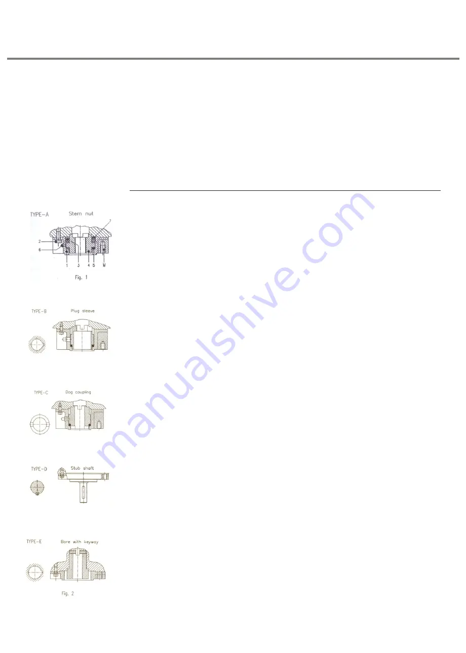
Output drives
Output drive type ‘A’ (Fig. 1)
This type is with stem nut. stem nut will be bored to pilot bore. Finish machining of nut to
be carried out by customer as follows:
•
Remove mounting flange (1)by loosening the bolts (2)
•
Loosen ring nut (3) after unlocking grub screw (7) and take out stem nut (4) along
with thrust bearings (5).
•
Drill, bore and cut threads as required.
•
Clean machined component and reassemble the output drive after applying ball
bearing grease to thrust bearings.
•
press grease through grease nipple (6) with grease gun.
•
Thoroughly clean the mounting faces of output drive and valve.
•
Apply small quantity of grease to stem of valve.
•
Assemble the output drive to valve stem by slowly rotating the stem nut by suitable
tool to engage the claws of the stem nut.
•
After full engagement of nut, clamp the output drive to valve by using suitable bolts
(threads at M).
•
Lower the actuator on to the output drive and rotate the hollow drive shaft of actuator
by engaging manual drive of actuator and rotating by hand wheel.
Output drive type B, C, D, E (Fig. 2):
Type B : Plug Sleeve
Type C : Dog coupling
Type D : Stub shaft
Type E : Bore with keyway
The above drives can be easily mounted to the actuator / gearbox as follows:
•
Check whether bore and keyway match the input shaft of valve or gearbox.
•
Output drive need not be removed from the actuator.
•
Place the actuator with output drive on to the valve and engage the output of
actuator (keyway or key of Type E) with the valve by slowly rotating the handwheel of
actuator after engaging manual drive.
•
Fasten valve flange to output drive flange with suitable bolts (bolt to at least quality
grade H8). Refer table ‘Tightening torque for bolts’ for approximate tightening
torques.
Weather proof actuators with 3.XMP-SIL &
Data logging
Содержание SA3-SA100
Страница 18: ...18 Weather proof actuators with 3 XMP SIL Data logging...
Страница 19: ...19 Weather proof actuators with 3 XMP SIL Data logging...
Страница 20: ...20 Weather proof actuators with 3 XMP SIL Data logging...
Страница 21: ...21 Weather proof actuators with 3 XMP SIL Data logging...
Страница 22: ...22 Weather proof actuators with 3 XMP SIL Data logging...
Страница 23: ...23 Weather proof actuators with 3 XMP SIL Data logging...
Страница 25: ...25 Weather proof actuators with 3 XMP SIL Data logging...
Страница 28: ...28 Weather proof actuators with 3 XMP SIL Data logging...
Страница 31: ...31 Weather proof actuators with 3 XMP SIL Data logging...
Страница 41: ...41 Wiring Diagram for SIL with Pro bus DP Weather proof actuators with 3 XMP SIL Data logging...
Страница 42: ...42 Wiring Diagram for SIL without Pro bus DP Weather proof actuators with 3 XMP SIL Data logging...
Страница 43: ...43 Wiring Diagram for SIL without Pro bus DP Weather proof actuators with 3 XMP SIL Data logging...
Страница 44: ...44 SIL Certi cate Weather proof actuators with 3 XMP SIL Data logging...
Страница 46: ...46 Weather proof actuators with 3 XMP SIL Data logging...
Страница 47: ...47 Weather proof actuators with 3 XMP SIL Data logging...


