


CHAPTER 13: FIELD REPLACEMENTS
DigiVu
®
Series Multichannel MPEG-2/H.264 Encoder/Multiplexer with QAM &/or IP Output - Installation & Operation Manual
13-1
FIELD REPLACEMENTS
13. Field Replacements
FYI:
Reference to DigiVu infers both DigiVu 3RU, DigiVu CD 3RU and DigiVu Mini 1RU unless
specifically stated.
13.1 Field Replacement of Realtime Clock Battery
All DigiVu models have a realtime backup battery access door on the
front panel. This battery maintains continuity of the clock on the DigiVu
main board in the event of power outages. The CMOS battery is Lithium
and has an expected life of 20+ years under normal system operation.
The DigiVu is shown but the procedure is the same for DigiVu Mini.
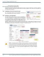
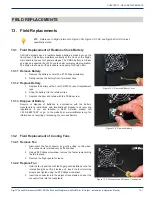
13.1.1 Remove Battery
1. Remove the battery cover with a #1 Phillips screwdriver.
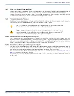
2. Gently remove the battery from its retainer clips.
13.1.2 Replace Battery
1. Replace the battery with a 3 volt CR 2032 or exact replacement
type.
2. Snap the battery into the retainer clips.
3. Replace the door and retain with the Phillips screw.
13.1.3 Dispose of Battery
Recycle or dispose of batteries in accordance with the battery
manufacturer’s instructions and local/national disposal and recycling
regulations. If you are located in North America, please call
1-800-8-BATTERY or go to the website at www.call2recycle.org for
information on recycling or disposing of your used battery.
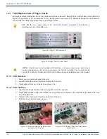
13.2 Field Replacement of Cooling Fans
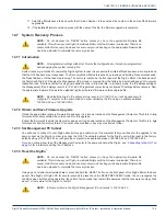
13.2.1 Remove Fan
1. Disconnect the fan connector by gently pulling on the wires.
The connector is retained only by friction clips.
2. Using a #2 Phillips screwdriver, remove the four screws holding
the fan in place.
3. Remove the finger guard for reuse.
13.2.2 Replace Fan
1. Hold the fan in position with the finger guard installed so the fan
rotates freely(do not flip it inside out), insert the four retaining
screws and tighten using the #2 Phillips screwdriver.
2. Insert the connector into the adjacent receptacle and seat the
connector fully into the receptacle.
Figure 13-1:
Remove Battery Cover
Figure 13-2:
Remove Battery
Figure 13-3:
Disconnect and Remove Cooling Fan


