


CHAPTER 11: IP OUTPUT TAB
DigiVu
®
Series Multichannel MPEG-2/H.264 Encoder/Multiplexer with QAM &/or IP Output - Installation & Operation Manual
11-7
11.10.3 Mng VLAN VID
This is the GUI VLAN ID
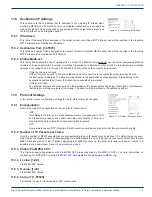
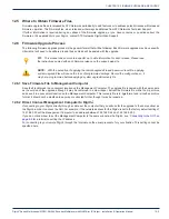
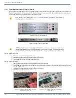
11.11 GbE Port Numbering
Physical ports on the Gigabit Ethernet card each have a number assigned for purposes of configuring VLANs as shown in
and described here:
1. Trunk Ports are both labeled #1 on the front panel.
Trunk ports will receive/transmit only tagged Ethernet packets which will be routed to their destination according to
their assigned VID. There is one each electrical and SFP (Small Form-Factor Pluggable) port which are identical
functionally and interchangeable depending on the type of interface required.
2. Terminal Ports are both labeled #2 on the front panel.
Terminal ports are connected to a device (such as the management port) that does not support VLAN tagging but
needs to be routed on a management VLAN. There is one each electrical and SFP port but the RJ45 port is typically
used in this case.
11.12 Two VLANs Automatically Created
Enabling the VLAN option automatically creates 2 VLANs over which the streaming video and the management of the DigiVu
device may be accessed over a single physical connection but kept separate at the destination switch.
1. Video LAN
The GbE video multiplex exists on this virtual LAN (it is connected to the switch through an internal port and the card
connector). This means that the MUX output is connected to an internal switch in the GigE Card. MUX output then
flows to both physical trunk ports; the ports labeled #1. These ports reside on the internal GbE switch so either may
be used as the trunk output.
2. Management LAN
Both physical Ports #2 of the GbE card are configured on this Virtual LAN. Either of these ports connect to the
Management Ethernet port through a straight wired Cat5e cable however typically only the RJ45 electrical port is
used. These ports are mutually exclusive so only one or the other may be used.
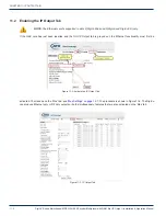
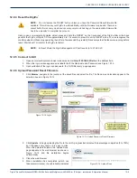
11.12.1 Quick Guide to VLAN Setup
a) Set up a remote external switch with VLAN support and
VLANs enabled for the GUI and streaming video.
b) On the DigiVu ‘IP Output’ tab select the
Active VLAN
check
box.
c) Set the VLAN VID for Mng (GUI) and Video VLAN VID to the
same VIDs used on the external switch.
d) Click
Submit
.
e) Connect the management IP port (from DigiVu Mini front
panel or the DiguVu 3RU back panel) to RJ45 GbE Port 2
on the GbE card using a short straight through Cat5e cable.
f) Connect one of the trunk ports labeled #1 (depends whether
you use copper or SFP) to a Trunk port on the external switch.
g) Connect a Management PC to the ‘Mng‘ management port at
the remote external switch and login to the GUI making sure
both the PC and DigiVu reside on the same subnet.
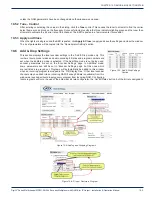
Figure 11-10:
GbE Card Port Numbering
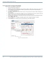
Figure 11-11:
Activate and Configure VLAN


