


CHAPTER 10: DEMOD & MUX SETTINGS TAB
10-4
DigiVu
®
Series Multichannel MPEG-2/H.264 Encoder/Multiplexer with QAM &/or IP Output - Installation & Operation Manual
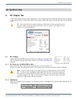
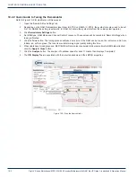
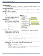
10.3 Demod & Mux Settings
The following is a description of the ‘Demod & Mux Settings‘
configuration page. The page is divided into 3 main sections
•
Demodulator Settings
•
Add & Drop Settings
•
PID Display Tree
Each of these screen sections are described next.
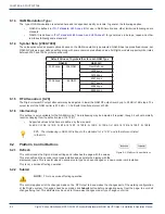
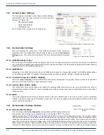
10.4 Demodulator Settings
This area displays the parameters of the QAM demodulator. These values are
adjustable in the ‘Tuner Diagnostic’ dialog that opens when you click the
Demodulator
Settings
button. That will be discussed below. The four parameters that are displayed
are:
10.4.1 QAM Modulation Type:
This is the type of QAM standard that the Demod will use and is determined mostly by locale and the Demod Card installed
(two versions are available); generally QAM B for North America and QAM A/C for Europe (and appropriate territories following
standards from North America/Europe/Japan).
10.4.2 QAM Mode:
Depending on the QAM Type selected above, the QAM mode is preset to a few possible values. For QAM-B available options
are 64 QAM and 256 QAM. For QAM-A/C available options are 16QAM, 32QAM, 64QAM, 128QAM and 256QAM.
10.4.3 Channel Frequency: [54000 - 866000]
This is the
center frequency
of the EIA/RF/CCIR channel to be demodulated. The possible values are 47000 kHz to 897000
kHz. Do not enter any commas or other punctuation marks.
10.4.4 Symbol Rate: [2608 - 6956]
The symbol rate of the QAM channel. For QAM-B for selected QAM mode there is only one valid symbol rate which is
automatically entered. For QAM-A/C, several possible symbol rates are preset and there is a possibility to enter a user defined
number as well.
10.4.5 BER:
This is the measured Bit Error Rate (or Bit Error Ratio) on the tuned QAM channel. This value should be very low, preferably
0.0E-08, indicating a quality signal. If the BER is worse than 1.0E-06 an investigation into transmission problems on the cable
system should be undertaken.
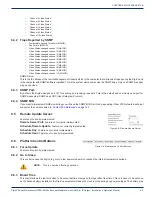
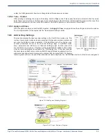
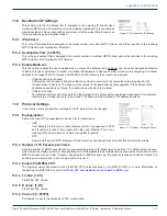
10.5 Demodulator Settings Buttons
10.5.1 Demodulator Settings
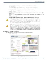
This control opens the
Tuner Diagnostics
window that permits changing the relevant
configuration and verifying the successful tuning of the specified QAM. The screen
“Quick Guide to Tuning the Demodulator” on page 10-2
outlines the process. The window contains
three indicators which are red by default when the window opens. Opening the Tuner Diagnostics window will always initially
display the three indicators as red, even when the tuner is currently properly tuned and locked. This screen must be refreshed
every time it is opened by clicking the
Tune
button. If the QAM demodulator cannot tune and lock on the carrier, the indicator
lights remain red, however, upon successful tuning and locking of sync, all three of the lights should be green and in a few
moments the BER (Bit Error rate) is measured and populated. The action of clicking the Tune button is not service affecting
Figure 10-4:
Demod and Mux Settings Configuration Page
Figure 10-5:
Demodulator Settings
Figure 10-6:
Demodulator Settings
Buttons


