


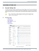


CHAPTER 4: INSTALLATION
4-4
DigiVu
®
Series Multichannel MPEG-2/H.264 Encoder/Multiplexer with QAM &/or IP Output - Installation & Operation Manual
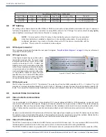
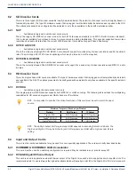
Fuse Replacement Criteria - All Models
Input Voltage
Model
Fuse application
Fuse Type
Ampere rating
Fuse size
115 VAC
All
AC IN
Slow Blow
3
5 x 20 mm glass tube
230 VAC
All
AC IN
Slow Blow
1.5
5 x 20 mm glass tube
4.8 RF Cabling
RF cabling to the chassis should be either RG6/u or RG59/u style double or triple shield coaxial cable of a type UL approved
for Cable TV applications. There is no restriction on using RG6/u cable on the F Fittings. Connectors should be
very lightly
wrench tightened according to Cable Service Provider’s company policy.
NOTE:
Final connection of the RF output to the distribution network should only be completed
when the installer has completed configuration. An incompatible configuration, if it was installed or
configured elsewhere, may create a situation where output RF Levels are incompatible with the
premises. This may result in unintended service outages.
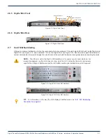
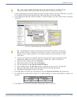
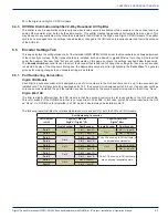
4.8.1 RF Output Connector
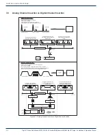
The accompanying graphic illustrates the rear panel. A diagram,
“Simplified Block Diagrams” on page 2-4
may be referenced
for details of interconnections.
4.8.2 RF Input Levels
If the DigiVu chassis has been fitted with a
demodulator module, then the input signal
level presented to the RF input of the module
must be in the range of +5 to +14 dBmV per
digital carrier as measured with a digital field
meter. If local conditions dictate that a higher
or lower signal level is available, the installer
must install appropriate external attenuation
or may install a coupler to ensure the input
specification is met. External RF attenuators
and couplers that may be necessary depend
on site conditions and are not supplied.
4.8.3 RF Output Level
The RF output connector is 75 Ω “F” Type female. The output level from the QAM modulator is 57.5 +/- 1.5 dBmV. The GUI
provides an internal adjustable attenuator of up to 26 dB in 1 dB steps to reduce this level to match application specific RF
levels. Try to adjust the modulator output QAM level to closely match adjacent channels on the final system combining network.
4.9 Audio & Video Connections
4.9.1 Video Cable Recommendation
Coaxial
It is recommended to utilize double or triple shielded 75 Ω coaxial cables with BNC or RCA (depending on encoder card)
connectors or adapters for video signals. UL approved coaxial cables that are in general use in Cable TV systems will usually
be satisfactory. Observe fire and smoke rating of cables and the installation environment to ensure compliance with all local
codes. Cables shall be routed and connectors and adapters attached such that terminal connections are not strained.
VGA
Usually a pre-manufactured VGA cable is used if this is the input signal type. Lengths up to about 50 meters may be available
but specify a plenum rated cable if the cables of this length which leave the equipment room will be installed. Cables shall be
routed and connectors and adapters attached such that terminal connections are not strained.
4.9.2 Video Port Connectors
The MPEG-2 encoders are provided with a BNC female connector for SD video input . For convenience a BNC male to RCA
female adapter is provided on each video input port as this is a common requirement in many installations.
The MPEG-2/H.264 encoders are provided with 3 x RCA female connector (component) and DE-15 female connector (VGA).
RF Out
Figure 4-2: DigiVu
®
Rear Panel RF Output


