


C 12
C.5.b. Pressure Relief Valve
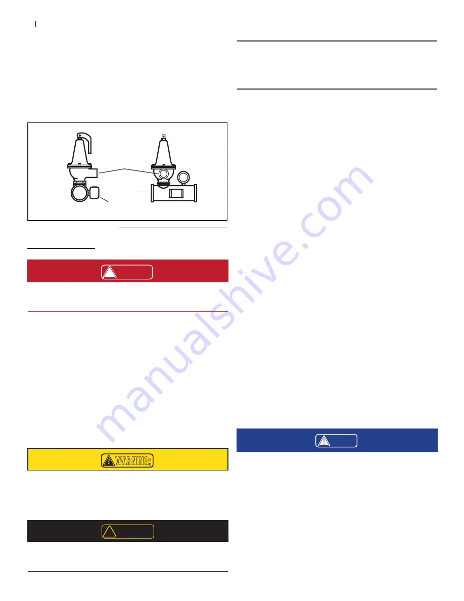
The pressure relief valve safety is factory assembled on the
safety manifold previously installed to the boiler in Section
C.2. Discharge piping must be installed to the relief valve
outlet to avoid potential scalding of attendants. Discharge
piping should be as short and direct as possible and in-
stalled and terminated per local codes and regulations.
Figure C.5.1. Manifold and Components
Manifold
Pressure Relief
Valve Outlet
FRONT
SIDE
Flow Switch
C.6. G
AS
S
UPPLY
!
DANGER:
Make sure the gas on which the boiler will operate is the
same as that speci ed on the boiler rating plate (natural
gas/propane).
•
The gas line should be a separate line running directly
from the gas meter to the unit, unless the existing gas
line is of ample capacity. Verify the capacity of the
existing gas piping if it is to be used.
•
The gas pipe must have a sediment trap ahead of the
boiler connection controls and a manual shut–off valve
located outside the boiler cabinet. It is highly recom-
mended that a union be installed in the gas supply
line adjacent to the boiler for servicing. The maximum
working gas pressure for both natural gas and propane
is 14” WC Keep in mind that an increase in gas pres-
sure, without making additional adjustments, leads to
an increased BTU input and a decreased ef ciency.
!
WARNING:
A sediment trap MUST be installed on the gas piping for
each gas line.
C.6.a. Testing Gas Line
!
CAUTION:
The boiler must be disconnected from the gas supply
during any pressure testing of the gas supply at test pres-
sures in excess of ½ psi (3.5 kPa).
The boiler must be isolated from the gas supply piping
system by closing its individual manual shut–off valve
during any pressure testing of the gas supply piping
system at test pressures equal to or more than ½ psi (3.5
kPa).
Do not use Te on tape on gas line thread. A pipe com-
pound rated for natural and propane gases are recom-
mended. Apply sparingly only on the male pipe ends,
leaving the two end threads bare.
Gas Piping Leak Test
Upon rst installing the Triton Series™ boiler, it is important
to check the gas line leading up to the unit for gas leaks.
1. Follow the National Fuel Gas Code for instructions on
proper gas line piping and gas leak tests.
2. Measuring gas pressures can help detect leaks in iso-
lated lines. Temporarily install a manometer or pressure
gauge with an upper limit of no more than 5 times the
testing pressure, 5 x 14” WC = 2.6psi for Triton Se-
ries™ boiler installations between the manual gas shut
off on the boiler and supply line’s regulator.
3. Leaving the shut off valve closed on the boiler, open
the supply line momentarily until the installed manom-
eter reads a stable pressure and record the pressure
and ambient temperature.
4. Close the supply line and monitor the gas pressure for
a drop in pressure. The test should be monitored for at
least 10 minutes or ½ hour per each 500 ft
3
of volume
in the testing pipe.
5. At the end of the monitoring period, record the gas
pressure and temperature. If there is a drop in pres-
sure, a gas leak may be present and should be further
investigated (Note: signi cant temperature variations
may cause changes in the gas pressure and should be
retested).
!
NOTE:
Please refer to the latest National Fuel Gas Code for
leak test details. If instructions differ, the Fuel Gas Code
shall supersede the instructions in section D.6.a. of these
instructions.
Содержание Triton T-80
Страница 31: ...E 29 E 3 ELECTICAL WIRING DIAGRAM ...
Страница 43: ...F 41 ...
Страница 44: ...F 42 ...
Страница 45: ...F 43 ...
Страница 46: ...F 44 Notes ...


