C
H A P T E R
1
M
A C H I N E
D
E S C R I P T I O N
2 0
6 7 1 0 D G
R I N D E R
O
P E R A T O R
S
A F E T Y
M
A N U A L
1 0 9 4 0 1 B
Material Feed
Important
Large non-grindable objects in the feed material
can cause down time and severe damage. For more
information, see “LIMITED WARRANTY POLICY”
on page 7 and “Responsibility for Safety” on
page 32.
At the core of the grinder, the machine uses an up-turn-
ing rotor in combination with a hydraulic, down-pres-
sure compression roll to grind the feed material in a
three-stage process:
1.
Compression by the feed system and impact by the
rotor bits, unless the material is solid, such as a
stump.
2.
Force against the anvil by the rotating bits.
3.
Force against and through the grates.
Adaptive Feed Control
The Peterson Adaptive Control System provides auto-
matic control of the feed system to ensure optimum
grinding efficiency. This system:
•
Monitors the grind load, varying the speed of the
feed system to keep the engine working at the top of
its power curve.
•
Accelerates the feed system when the engine load is
light, slows it when the load is high, and stops or
reverses the feed.
•
Monitors the engine temperature and varies the
cooling fan speed accordingly.
For more details, see “Peterson Adaptive Control Sys-
tem” on page 129.
Hopper
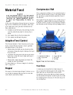
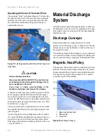
The design of the feed hopper (Figure 9) allows you to
use a loader for placing bulky material over the side
walls directly onto the feed chain.
Compression Roll
The compression roll (Figure 9), located at the head of
the feed chain and at the entrance to the grinder assem-
bly, operates to contain the feed material and force it
into the rotor.
The weight of the compression roll as it rides on top of
the material, combined with a downward pressure by a
hydraulic cylinder, condenses loose material and breaks
up other items as the first stage in the grinding process.
Figure 9:
Hopper and Feed Assembly
Feed Chain
A continuous and reversible feed chain (Figure 9)
moves material from the hopper into the grinder. The
feed chain is moved by the feed conveyor drive.
The adaptive feed system effectively meters material
into the grinder at the highest rate the engine can sustain
by automating the feed conveyor’s forward, stop, and
reverse functions.
F10440
6
5
1
2
3
4
1. Compression Roll (Raised)
2. Feed Conveyor Drive
3. Rotor
4. Hopper, Side Wall
5. Feed Chain
6. Tail Pulley
Содержание Peterson 6710D
Страница 6: ...C O N T E N T S 4 67 1 0 D G R I N D E R O P E R A T O R SA F E T Y M A N U A L 109401B ...
Страница 10: ...A B O U T TH I S M A N U A L 8 67 1 0 D G R I N D E R O P E R A T O R SA F E T Y M A N U A L 109401B ...
Страница 158: ...16 2 67 1 0 D G R I N D E R O P E R A T O R SA F E T Y M A N U A L 109401B ...
Страница 166: ...I N D E X 17 0 67 1 0 D G R I N D E R O P E R A T O R SA F E T Y M A N U A L 109401B ...
Страница 167: ......


