Platform Architecture
AXP640 Installation and Use (6806800M24F
)
46
1.4.4
Update Channel Interface
The update channel interface consists of 10 differential pairs on the P20 connector. The
physical layer and protocol used on this interface is application specific.
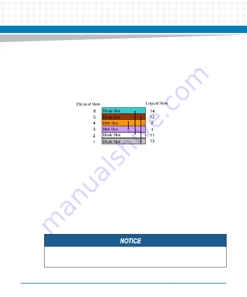
illustrates
the update channel inter-connectivity.
1.5
Backplane and Component Connectivity
The blade connectivity on the AXP640 backplane is divided among three zones, each with the
following characteristics:
Zone 1 provides redundant, radial IPMI to all blade slots and redundant -48 VDC to all blade
slots
Zone 2, the data transport interface, provides the dual star configuration for the base
interface, dual star configuration for the fabric interface, update channel routing for all
blade slots, and three redundant, bussed telecom clock signals to all blade slots
Zone 3 provides the PICMG 3.0 defined open area that is application specific
Figure 1-1
Update Channel
Rear Transition Modules connect directly with the connectors on the front-side blade and do
not make the connection through the backplane.
Содержание AXP640
Страница 1: ...AXP640 Installation and Use P N 6806800M24F May 2014 ...
Страница 8: ...AXP640 Installation and Use 6806800M24F Contents 8 Contents Contents ...
Страница 10: ...AXP640 Installation and Use 6806800M24F 10 List of Tables ...
Страница 50: ...Platform Architecture AXP640 Installation and Use 6806800M24F 50 ...
Страница 53: ...AXP640 Shelf Description AXP640 Installation and Use 6806800M24F 53 Figure 2 2 DC Rear Shelf View ...
Страница 69: ...AXP640 Shelf Description AXP640 Installation and Use 6806800M24F 69 Figure 2 13 AC Inlet Markings 110V ...
Страница 70: ...AXP640 Shelf Description AXP640 Installation and Use 6806800M24F 70 Figure 2 14 AC Inlet 220V ...
Страница 77: ...AXP640 Shelf Description AXP640 Installation and Use 6806800M24F 77 Figure 2 18 DC Rating Label ...
Страница 78: ...AXP640 Shelf Description AXP640 Installation and Use 6806800M24F 78 Figure 2 19 AC Rating Label ...
Страница 90: ...Site Preparation AXP640 Installation and Use 6806800M24F 90 Figure 3 2 ETSI Frame Mount Rear View ...
Страница 91: ...Site Preparation AXP640 Installation and Use 6806800M24F 91 Figure 3 3 ETSI Frame Mount Side View ...
Страница 92: ...Site Preparation AXP640 Installation and Use 6806800M24F 92 Figure 3 4 19 inch Frame Front Mount Front View ...
Страница 93: ...Site Preparation AXP640 Installation and Use 6806800M24F 93 Figure 3 5 19 inch Frame Mid mount Front View ...
Страница 94: ...Site Preparation AXP640 Installation and Use 6806800M24F 94 Figure 3 6 19 23 inch Frame Mid mount Side View ...
Страница 95: ...Site Preparation AXP640 Installation and Use 6806800M24F 95 Figure 3 7 23 inch Frame Front Mount Front View ...
Страница 101: ...Site Preparation AXP640 Installation and Use 6806800M24F 101 Figure 3 13 Planning Checklist 2 ...
Страница 102: ...Site Preparation AXP640 Installation and Use 6806800M24F 102 ...
Страница 112: ...AXP640 Operations AXP640 Installation and Use 6806800M24F 112 ...
Страница 136: ...AXP640 Shelf Installation AXP640 Installation and Use 6806800M24F 136 ...
Страница 164: ...FRU Installation AXP640 Installation and Use 6806800M24F 164 ...
Страница 186: ...Shelf Management Alarm Module AXP640 Installation and Use 6806800M24F 186 ...
Страница 189: ......

