


FRU Installation
AXP640 Installation and Use (6806800M24F
)
156
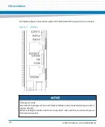
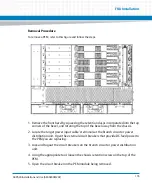
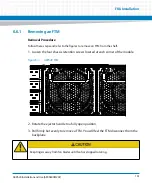
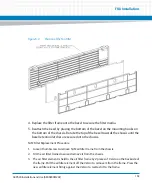
6. Open the ejector handle and gently pull on the PEM module. You will feel the PEM
disconnect from the backplane.
7. Pull the module straight out from the rail guides, about 12 inches.
6.4.3
Installation Procedure
To install a power entry module, follow the steps below:
1.
If not already removed, remove the front bezel by squeezing the retention clasps
incorporated into the top corners of the bezel and rotating the top of the bezel
away from the chassis.
2.
Insure the replacement PEM circuit breaker is in the open position.
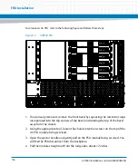
3.
Align the PEM with the guide rails on the power bay that the PEM will be inserted
into.
4. Slide the module straight in on the guide rails, about 12 inches. You will feel the
PEM engage the backplane connector.
5. Secure the PEM with the chassis retention screw at the top of the PEM module.
6. Rotate the PEM handle down so that it is flush with the front of the PEM module.
7. Close the PEM circuit breaker.
8. Remove the lock and tagout from the circuit breakers on the branch circuit or
power distribution unit, and return power to the appropriate chassis power feed.
The DC PEMs will only engage a backplane connector in power bay A2 and B1 (PBA2 and
PBA1) Power bay A1 and B2 (PBA1 and PBB2) are required to have power bay slot fillers
installed.
Содержание AXP640
Страница 1: ...AXP640 Installation and Use P N 6806800M24F May 2014 ...
Страница 8: ...AXP640 Installation and Use 6806800M24F Contents 8 Contents Contents ...
Страница 10: ...AXP640 Installation and Use 6806800M24F 10 List of Tables ...
Страница 50: ...Platform Architecture AXP640 Installation and Use 6806800M24F 50 ...
Страница 53: ...AXP640 Shelf Description AXP640 Installation and Use 6806800M24F 53 Figure 2 2 DC Rear Shelf View ...
Страница 69: ...AXP640 Shelf Description AXP640 Installation and Use 6806800M24F 69 Figure 2 13 AC Inlet Markings 110V ...
Страница 70: ...AXP640 Shelf Description AXP640 Installation and Use 6806800M24F 70 Figure 2 14 AC Inlet 220V ...
Страница 77: ...AXP640 Shelf Description AXP640 Installation and Use 6806800M24F 77 Figure 2 18 DC Rating Label ...
Страница 78: ...AXP640 Shelf Description AXP640 Installation and Use 6806800M24F 78 Figure 2 19 AC Rating Label ...
Страница 90: ...Site Preparation AXP640 Installation and Use 6806800M24F 90 Figure 3 2 ETSI Frame Mount Rear View ...
Страница 91: ...Site Preparation AXP640 Installation and Use 6806800M24F 91 Figure 3 3 ETSI Frame Mount Side View ...
Страница 92: ...Site Preparation AXP640 Installation and Use 6806800M24F 92 Figure 3 4 19 inch Frame Front Mount Front View ...
Страница 93: ...Site Preparation AXP640 Installation and Use 6806800M24F 93 Figure 3 5 19 inch Frame Mid mount Front View ...
Страница 94: ...Site Preparation AXP640 Installation and Use 6806800M24F 94 Figure 3 6 19 23 inch Frame Mid mount Side View ...
Страница 95: ...Site Preparation AXP640 Installation and Use 6806800M24F 95 Figure 3 7 23 inch Frame Front Mount Front View ...
Страница 101: ...Site Preparation AXP640 Installation and Use 6806800M24F 101 Figure 3 13 Planning Checklist 2 ...
Страница 102: ...Site Preparation AXP640 Installation and Use 6806800M24F 102 ...
Страница 112: ...AXP640 Operations AXP640 Installation and Use 6806800M24F 112 ...
Страница 136: ...AXP640 Shelf Installation AXP640 Installation and Use 6806800M24F 136 ...
Страница 164: ...FRU Installation AXP640 Installation and Use 6806800M24F 164 ...
Страница 186: ...Shelf Management Alarm Module AXP640 Installation and Use 6806800M24F 186 ...
Страница 189: ......


