


Shelf Management Alarm Module
AXP640 Installation and Use (6806800M24F
)
176
Cross connected redundant ShMM-1500R status 1 input (SHMM_STATUS1_R) and output
(SHMM_STATUS1_L)
Active output (ACTIVE#) that can be used on the ShMM-1500R carrier to enable interfaces
that must be exclusively driven by the active ShMM-1500R
Bi-color status LED
The cross-connected ShMM-1500R status signals are asynchronous serial bit streams that are
transmitted to the peer-ShMM by the FPGA and communicate the following information:
Health status, Switchover Requests, PRES_R state, Active state, watchdog timer status, parity
and other data. An identical copy of the bit stream is also sent on the redundant ShMM-1500R
status signal. This information is used to ensure that only one of the two connected ShMM-
1500Rs goes into active mode at a time.
shows the HRI of the ShMM-
1500R.
As shown in the figure, the ShMM-1500R HRI incorporates a hot-swap buffer (IDT
QuickSwitch), which isolates the interface from the peer ShMM prior to FPGA configuration or
when the ShMM-1500R is powered down. The QuickSwitch device is guaranteed to be disabled
(open) when unpowered and does not have a low impedance path from any of the signal pins
to the power or ground rails. Hence, the device prevents an unpowered ShMM-1500R from
loading down the HRI of the peer ShMM-1500R. It also prevents a carrier from detecting the
ACTIVE# output as a zero; that is, active, during a ShMM-1500R power cycle or a ShMM-1500R
power supply failure.
Содержание AXP640
Страница 1: ...AXP640 Installation and Use P N 6806800M24F May 2014 ...
Страница 8: ...AXP640 Installation and Use 6806800M24F Contents 8 Contents Contents ...
Страница 10: ...AXP640 Installation and Use 6806800M24F 10 List of Tables ...
Страница 50: ...Platform Architecture AXP640 Installation and Use 6806800M24F 50 ...
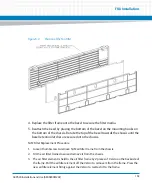
Страница 53: ...AXP640 Shelf Description AXP640 Installation and Use 6806800M24F 53 Figure 2 2 DC Rear Shelf View ...
Страница 69: ...AXP640 Shelf Description AXP640 Installation and Use 6806800M24F 69 Figure 2 13 AC Inlet Markings 110V ...
Страница 70: ...AXP640 Shelf Description AXP640 Installation and Use 6806800M24F 70 Figure 2 14 AC Inlet 220V ...
Страница 77: ...AXP640 Shelf Description AXP640 Installation and Use 6806800M24F 77 Figure 2 18 DC Rating Label ...
Страница 78: ...AXP640 Shelf Description AXP640 Installation and Use 6806800M24F 78 Figure 2 19 AC Rating Label ...
Страница 90: ...Site Preparation AXP640 Installation and Use 6806800M24F 90 Figure 3 2 ETSI Frame Mount Rear View ...
Страница 91: ...Site Preparation AXP640 Installation and Use 6806800M24F 91 Figure 3 3 ETSI Frame Mount Side View ...
Страница 92: ...Site Preparation AXP640 Installation and Use 6806800M24F 92 Figure 3 4 19 inch Frame Front Mount Front View ...
Страница 93: ...Site Preparation AXP640 Installation and Use 6806800M24F 93 Figure 3 5 19 inch Frame Mid mount Front View ...
Страница 94: ...Site Preparation AXP640 Installation and Use 6806800M24F 94 Figure 3 6 19 23 inch Frame Mid mount Side View ...
Страница 95: ...Site Preparation AXP640 Installation and Use 6806800M24F 95 Figure 3 7 23 inch Frame Front Mount Front View ...
Страница 101: ...Site Preparation AXP640 Installation and Use 6806800M24F 101 Figure 3 13 Planning Checklist 2 ...
Страница 102: ...Site Preparation AXP640 Installation and Use 6806800M24F 102 ...
Страница 112: ...AXP640 Operations AXP640 Installation and Use 6806800M24F 112 ...
Страница 136: ...AXP640 Shelf Installation AXP640 Installation and Use 6806800M24F 136 ...
Страница 164: ...FRU Installation AXP640 Installation and Use 6806800M24F 164 ...
Страница 186: ...Shelf Management Alarm Module AXP640 Installation and Use 6806800M24F 186 ...
Страница 189: ......


