AXP640 Operations
AXP640 Installation and Use (6806800M24F
)
108
Sentry Shelf Management software. Refer to the
AXP640 Subsystem IPMI Programmer’s
Reference
guide listed in
for more information.
4.6
Fan Tray Modules
This section discusses the operation of the Fan Tray Modules (FTMs) of the AXP640.
4.6.1
Description
The FTMs are loaded with AdvancedTCA IPMC firmware. The fans are controlled as a group
through the IPMI-based interfaces (IPMB) to the SAM. The IPMI interface is used for reporting
faults, events, and status.The shelf manager software performs management of the FTM
through the IPMB bus.The IPMC circuit provides temperature sensors for monitoring the
temperatures of the FTM board components and for monitoring the inlet and outlet air
temperature of the shelf. For further information, refer to the
AXP640 Subsystem IPMI
Programmer’s Reference
guide listed in
The FTMs have variable speed fan control, which is dependent on the temperature readings in
the shelf. Airflow rates can vary depending on the fan speed and payload. Fan speed levels are
controlled from the SAM through the IPM shelf management software. The fan speed levels
change automatically based on temperature sensors. For more information, refer to
Each FTM is equipped with a single bi-colored status LED on the face plate. For removal and
installation procedures for the FTMs, refer to
In the event of a FanOut-of-Service alarm, first check the fan filters to make sure the airflow is
not obstructed. For information on the maintenance of air filters, see
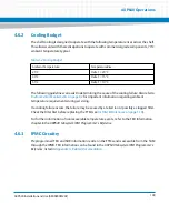
Table 4-1 PEM IPMB Addresses
Description
IPMB Address
PEM A
0x66
PEM B
0x68
Содержание AXP640
Страница 1: ...AXP640 Installation and Use P N 6806800M24F May 2014 ...
Страница 8: ...AXP640 Installation and Use 6806800M24F Contents 8 Contents Contents ...
Страница 10: ...AXP640 Installation and Use 6806800M24F 10 List of Tables ...
Страница 50: ...Platform Architecture AXP640 Installation and Use 6806800M24F 50 ...
Страница 53: ...AXP640 Shelf Description AXP640 Installation and Use 6806800M24F 53 Figure 2 2 DC Rear Shelf View ...
Страница 69: ...AXP640 Shelf Description AXP640 Installation and Use 6806800M24F 69 Figure 2 13 AC Inlet Markings 110V ...
Страница 70: ...AXP640 Shelf Description AXP640 Installation and Use 6806800M24F 70 Figure 2 14 AC Inlet 220V ...
Страница 77: ...AXP640 Shelf Description AXP640 Installation and Use 6806800M24F 77 Figure 2 18 DC Rating Label ...
Страница 78: ...AXP640 Shelf Description AXP640 Installation and Use 6806800M24F 78 Figure 2 19 AC Rating Label ...
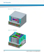
Страница 90: ...Site Preparation AXP640 Installation and Use 6806800M24F 90 Figure 3 2 ETSI Frame Mount Rear View ...
Страница 91: ...Site Preparation AXP640 Installation and Use 6806800M24F 91 Figure 3 3 ETSI Frame Mount Side View ...
Страница 92: ...Site Preparation AXP640 Installation and Use 6806800M24F 92 Figure 3 4 19 inch Frame Front Mount Front View ...
Страница 93: ...Site Preparation AXP640 Installation and Use 6806800M24F 93 Figure 3 5 19 inch Frame Mid mount Front View ...
Страница 94: ...Site Preparation AXP640 Installation and Use 6806800M24F 94 Figure 3 6 19 23 inch Frame Mid mount Side View ...
Страница 95: ...Site Preparation AXP640 Installation and Use 6806800M24F 95 Figure 3 7 23 inch Frame Front Mount Front View ...
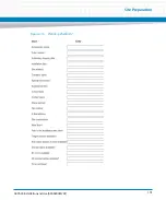
Страница 101: ...Site Preparation AXP640 Installation and Use 6806800M24F 101 Figure 3 13 Planning Checklist 2 ...
Страница 102: ...Site Preparation AXP640 Installation and Use 6806800M24F 102 ...
Страница 112: ...AXP640 Operations AXP640 Installation and Use 6806800M24F 112 ...
Страница 136: ...AXP640 Shelf Installation AXP640 Installation and Use 6806800M24F 136 ...
Страница 164: ...FRU Installation AXP640 Installation and Use 6806800M24F 164 ...
Страница 186: ...Shelf Management Alarm Module AXP640 Installation and Use 6806800M24F 186 ...
Страница 189: ......


