FRU Installation
AXP640 Installation and Use (6806800M24F)
159
6.5.2
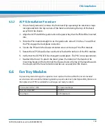
AC PSU Installation Procedure
1.
If not already removed, remove the front bezel by squeezing the retention clasps
incorporated into the top corners of the bezel and rotating the top of the bezel
away from the chassis.
2. Align the AC PSU with the guide rails on the power bay that the PSU will be inserted
into.
3. Slide the PSU module straight in on the guide rails, about 12 inches. You will feel
the PSU engage the backplane connector.
4. Secure the PSU with the chassis retention screw at the top of the PSU module.
5. Rotate the AC PSU handle down so that it is flush with the front of the PSU module.
6. Verify that the AC PSU LED has changed to solid green. The PSU is now operational.
7.
Reattach the bezel. To attach the bezel, place the bottom of the bezel on the
mounting hooks on the bottom of the chassis. Rotate the top of the bezel towards
the chassis until the bezel retention latches are secured into the chassis.
6.6
Fan Tray Modules
To prevent system damage, the operator must replace the fans within the recommended
service interval shown in the following table to prevent a decline in shelf operability. Make sure
the replacement FTM is available for exchange and ready to install.
Service Interval for 1 FTM
Temperature Range
Not recommended
40-55°C
Four hours
40°C maximum
Содержание AXP640
Страница 1: ...AXP640 Installation and Use P N 6806800M24F May 2014 ...
Страница 8: ...AXP640 Installation and Use 6806800M24F Contents 8 Contents Contents ...
Страница 10: ...AXP640 Installation and Use 6806800M24F 10 List of Tables ...
Страница 50: ...Platform Architecture AXP640 Installation and Use 6806800M24F 50 ...
Страница 53: ...AXP640 Shelf Description AXP640 Installation and Use 6806800M24F 53 Figure 2 2 DC Rear Shelf View ...
Страница 69: ...AXP640 Shelf Description AXP640 Installation and Use 6806800M24F 69 Figure 2 13 AC Inlet Markings 110V ...
Страница 70: ...AXP640 Shelf Description AXP640 Installation and Use 6806800M24F 70 Figure 2 14 AC Inlet 220V ...
Страница 77: ...AXP640 Shelf Description AXP640 Installation and Use 6806800M24F 77 Figure 2 18 DC Rating Label ...
Страница 78: ...AXP640 Shelf Description AXP640 Installation and Use 6806800M24F 78 Figure 2 19 AC Rating Label ...
Страница 90: ...Site Preparation AXP640 Installation and Use 6806800M24F 90 Figure 3 2 ETSI Frame Mount Rear View ...
Страница 91: ...Site Preparation AXP640 Installation and Use 6806800M24F 91 Figure 3 3 ETSI Frame Mount Side View ...
Страница 92: ...Site Preparation AXP640 Installation and Use 6806800M24F 92 Figure 3 4 19 inch Frame Front Mount Front View ...
Страница 93: ...Site Preparation AXP640 Installation and Use 6806800M24F 93 Figure 3 5 19 inch Frame Mid mount Front View ...
Страница 94: ...Site Preparation AXP640 Installation and Use 6806800M24F 94 Figure 3 6 19 23 inch Frame Mid mount Side View ...
Страница 95: ...Site Preparation AXP640 Installation and Use 6806800M24F 95 Figure 3 7 23 inch Frame Front Mount Front View ...
Страница 101: ...Site Preparation AXP640 Installation and Use 6806800M24F 101 Figure 3 13 Planning Checklist 2 ...
Страница 102: ...Site Preparation AXP640 Installation and Use 6806800M24F 102 ...
Страница 112: ...AXP640 Operations AXP640 Installation and Use 6806800M24F 112 ...
Страница 136: ...AXP640 Shelf Installation AXP640 Installation and Use 6806800M24F 136 ...
Страница 164: ...FRU Installation AXP640 Installation and Use 6806800M24F 164 ...
Страница 186: ...Shelf Management Alarm Module AXP640 Installation and Use 6806800M24F 186 ...
Страница 189: ......


