34
Utility Software
7.4
Establishing a Serial Connection
NOTE:
A null-modem cable is needed to connect with the clock to the computer’s serial port. Pin
connections and functions are as follows:
PC side
–
Clock side
3, TxD
–
2, RxD
2, RxD
–
3, TxD
5, GND
–
5, GND
Table 7.2: Serial Cable Pin Out
For computers without a serial port, you will most likely need to use a USB to serial converter.
These devices normally associate a COM port number (on your computer) with the USB device.
For the Windows operating systems, you may look this up under
Device Manager
>
Ports
.
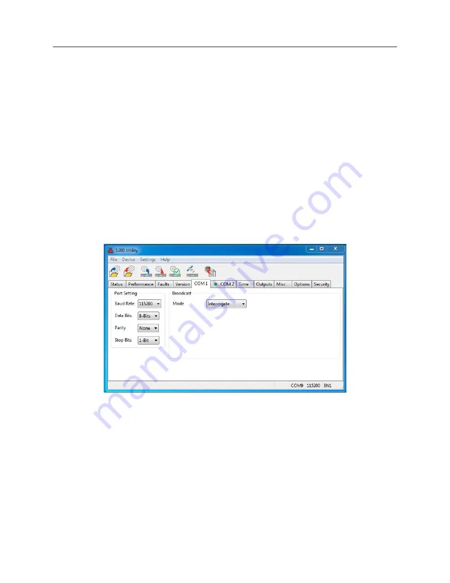
From the Utility, select
Settings
>
Serial Port
, choosing the correct COM port associated with
your computer. See Figure 7.2. If your computer has its own serial port, choose that one. If
you are using a USB-to-serial converter, choose the one that is associated with your USB-to-Serial
converter.
Figure 7.2: Connecting with the Clock
Verify that the baud rate listed under Serial Port Settings is the same as on the clock. To verify
the baud rate from the front panel of your clock, security must be set to Level 0 or 1. Press the
SETUP key on the clock; the first menu should state, “SET SERIAL COM 1?”; press SETUP
again and the second menu should state “SET SERIAL COM 2?” Press ENTER at “SET SERIAL
COM 1” or “SET SERIAL COM 2” to verify the port parameters for either COM1 or COM2.
Содержание 1200B
Страница 4: ...iv ...
Страница 135: ...A 3 Physical Dimensions 117 Figure A 2 Suggested Mounting of the GNSS Surge Arrester ...
Страница 143: ...B 7 Four Fiber Optic Outputs 125 Figure B 4 Jumper Locations ...
Страница 145: ...B 8 8 Channel High Drive IRIG B Amplifier 127 Figure B 5 8 High Drive Outputs Jumper Locations ...
Страница 161: ...B 10 Four Additional Outputs and Dry Contacts 25 50 Vdc 143 Figure B 7 Option Connector Signal Locations ...
Страница 212: ...Appendix E Statement of Compliance The following page is a statement of compliance that includes Model 1201B and 1201C ...


