background image

30

10.1 

IMPLEMENT ADVANCED SETTINGS

10.1.1 

Spray spots configurations

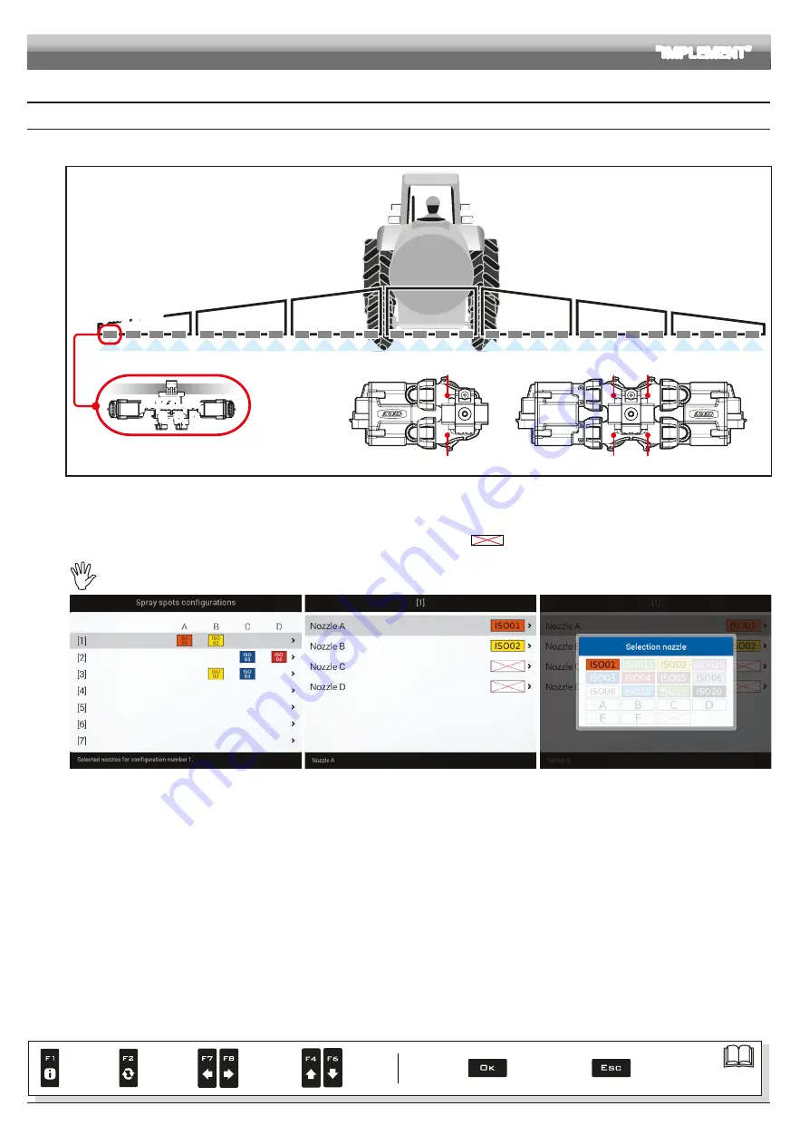
Allows setting 20 different configurations (i.e., 20 nozzle combinations), which can be selected before starting each job.
Each configuration indicates which type of nozzle is installed on the boom's spraying points.

NOZZLES

A, B, C, D

Spraying point

Nozzle A

Nozzle C

Nozzle B

Nozzle D

Nozzle A

Nozzle B

Fig. 75 

During guided setup (chap. 9), the computer will ask you to indicate which type of Seletron is installed at said spraying points (single, twin or fourfold).
Depending on the selected option the number of nozzles to be programmed in this menu will vary.

- Select the configuration you wish to set up (Fig. 76).
- Select the nozzle you wish to set up (

A

B

C

 or 

D

, in Fig. 77).

- Select one of the suggested nozzles (Fig. 78): if a nozzle is NOT in use, disable it by selecting 

.

- Repeat the setup for each configuration. 

 The nozzle settings are the same for all spraying points on the boom.

Fig. 76

Fig. 77

Fig. 78

ADVANCED SETUP 

"IMPLEMENT"

Par.

7.4

Confirm access 
or data change

Exit the function or 
data change

Delete 
selected 
character

Scroll
(LEFT / 
RIGHT)

Data
increase /
decrease

Scroll
(UP / 
DOWN)

Enter 
selected 
character

Содержание DELTA 80

Страница 1: ...INSTALLATION USE AND MAINTENANCE 4675000 DELTA 80 COMPUTER WITH INTEGRATED GPS NAVIGATOR Software rel 2 7X When matched to a remote control unit of the SELETRON IBX100 SERIES...

Страница 2: ...part of the equipment to which it refers and must accompany the equipment in case of sale or change of ownership Keep it for any future reference ARAG reserves the right to modify product specificatio...

Страница 3: ...pe 35 Maximum pressure 35 10 1 6 Valves 36 MAIN VALVE Type REMINDER 36 Automatic closing of sections valves REMINDER 36 Automatic closing of main valve 36 Switching time 36 PRESSURE REGULATING VALVE R...

Страница 4: ...t adjustment 79 13 2 F2 Automatic adjustment ON OFF 79 13 3 Importing and using a prescription map 79 13 4 How the automatic nozzle selection works SELETRON system 80 13 5 F4 Automatic nozzle selectio...

Страница 5: ...zed with 2004 108 EC Directive 3 PRECAUTIONS Do not aim water jets at the equipment Do not use solvents or fuel to clean the case outer surface Do not clean equipment with direct water jets Comply wit...

Страница 6: ...ELETRON SYSTEM WITHOUT HYDRAULIC CONTROLS Legend of connection cables 1A Computer ECU battery for TOWED MACHINE 1B Computer ECU battery for SELF PROPELLED MACHINE 2 Sensors control unit 3 Head end cab...

Страница 7: ...nation cable 6 Hydraulic ECU 7 Hydraulic unit 8a Computer switch panel 8b Computer switch panel cameras general external control 9 GPS receiver S Speed sensor T Filling flowmeter X RPM sensor L Level...

Страница 8: ...A051 100 5 3 0 5 467 493 A061 100 6 3 5 1 467 493 A071 100 7 4 0 5 467 493 A081 100 8 4 5 1 CABLES FOR SELETRON TWIN FOURFOLD MAX BOOM WIDTH 24 M 50 cm spacing 3 CENTRAL CABLES Code no of SELETRON no...

Страница 9: ...control units on the back of the machine close to the control unit and the hydraulic unit Consider all necessary connections of the computer Fig 4 Fig 5 Fig 6 and Fig 7 the cable length and make sure...

Страница 10: ...ioning ITEM CONNECTION POINTS IBX100 ECU SPRAYER 8 Control unit G P Sensors 9a Control unit water valves 10a Hydraulic unit 9b Seletron Line 2 10b Seletron Line 1 11 Monitor power supply IBX100 ECU Hy...

Страница 11: ...he ECU using the 4 bolts fitted into their slots A Fig 9 No other type of position is allowed Fig 9 5 5 Control unit position The control unit must be fixed with the special brackets supplied and fitt...

Страница 12: ...the connection points do not force the connectors by pushing too hard or bending them the contacts may be damaged and computer operation may be compromised Use ONLY the cables and accessories indicate...

Страница 13: ...cated cables for the type of Seletron installed Tab 1 CONNECTION CABLES on page 8 WARNING THE CABLES DESIGNED FOR CONNECTING TWIN SELETRON UNITS ON BOOMS UP TO 24 M LONG SHOULD NEVER BE USED ON LONGER...

Страница 14: ...tors B Fig 17 9 Secure the branches to the boom threading the ties through the suitable recesses Fig 18 10 When installing a twin or fourfold nozzle holder make sure that all connectors are facing the...

Страница 15: ...be held responsible for any damage to the system people animals or objects caused by failure to follow the guidelines outlined above 6 5 Hydraulic valve connection Delta 80 can control up to 9 hydraul...

Страница 16: ...push it until locking it Fig 22 Fig 23 6 7 Camera connection Delta 80 can be connected to one or two cameras code 46700100 purchased separately using the suitable cables listed in the ARAG general cat...

Страница 17: ...rect positioning might cause water seepage inside the monitor Fig 25 Insertion Insert the SIM card making sure to orient it correctly the card cut edge D must be face up push the card until it engages...

Страница 18: ...RING THE PAIRING PROCEDURE chap 11 Seletron connection 7 2 Switching on Fig 26 Fig 27 SOFTWARE VERSION Fig 28 Hold the button at the back of the monitor down for 3 seconds after a few seconds Delta 80...

Страница 19: ...g 34 Hold the button at the back of the monitor down until Delta 80 switches off During switching off Delta 80 automatically saves the current job Do NOT press any other key and do NOT disconnect the...

Страница 20: ...without confirming modification ENTERING TEXT 2 1B 3 1A 1A 1B 5 4 B A Fig 37 1A Press in succession to select the character you wish to type UP DOWN 1B Press in succession to select the character you...

Страница 21: ...created settings chap 9 System setup chap 14 Home Menu chap 10 Advanced setup chap 9 Basic settings Create Load settings User usrxx Configuration macxx impxx traxx type of configuration displayed chan...

Страница 22: ...d press OK twice new user is now active on the computer usr00 Go to step 2 Fig 40 OK Next step ESC Previous step Fig 41 Fig 42 2 SAVING THE MACHINE CONFIGURATION Select Configuration Fig 43 follow the...

Страница 23: ...OK Next step ESC Previous step Fig 51 BASIC SETTINGS IMPLEMENT TYPE Sprayer Seletron system with Seletron valves Sprayer Electrovalves system with electric activated valves with gearmotor MAIN VALVE M...

Страница 24: ...completed Press OK GUIDANCE SETTINGS AUTONOMOUS GUIDANCE control unit for automatic guidance GeoSteer control unit with built in control unit ECU S1 ARAG control unit code 4679100 None GPS RECEIVER A...

Страница 25: ...vated valves with gearmotor MAIN VALVE Main control valve installed on the control unit None 2 ways drain valve 3 ways main valve SPRAYING SPOT TYPE Seletron type single twin or fourfold FLOWRATE REFE...

Страница 26: ...r code 520100 693 Smart Ag Smart 6 ARAG receivers code 467016xx AgStar ARAG receivers code 467016xx NMEA all GPS receivers with NMEA183 protocol and with the following features 10 Hz GGA message latit...

Страница 27: ...uggested steps and select required options OK next step ESC previous step Type the name in the example of Fig 64 usr01 and press OK The new setup is now active on the computer Fig 65 Before moving on...

Страница 28: ...previous step The selected setup is now active on the computer Fig 71 Proceed to advanced setup You can repeat the same steps for setup Load User e d e Fig 69 Fig 70 Fig 71 You can now proceed with a...

Страница 29: ...IMPLEMENT 2 2 3 Fig 73 2 2 3 Fig 74 SELF PROPELLED IMPLEMENT ADVANCED SETTINGS par 10 1 GPS RECEIVER SETTINGS par 10 3 AUTONOMOUS GUIDANCE par 10 4 TRACTOR ADVANCED SETTINGS par 10 5 USER par 10 6 GEN...

Страница 30: ...said spraying points single twin or fourfold Depending on the selected option the number of nozzles to be programmed in this menu will vary Select the configuration you wish to set up Fig 76 Select t...

Страница 31: ...oom sprayer Boom sprayer Fig 80 Fig 81 Depending on the selected settings the number of spraying points as well as the value of the boom width displayed in Fig 81 will change Boom width Fig 82 Fig 83...

Страница 32: ...tion status of the sections It allows to enable disable specific boom sections Section enabled Section disabled Select the section you wish to set up Repeat the setup for each section Fig 86 by disabl...

Страница 33: ...3 400 105 7 462xxA4xxxx 300 1135 10 2 60 200 52 8 462x7xxx 60 227 40 0 10 6 800 211 3 4622xA5xxxx 150 568 20 5 30 400 105 7 4622xA6xxxx 100 378 30 7 90 600 158 5 Other 625 2366 10 2 60 200 52 8 Fig 88...

Страница 34: ...l l min GPM l min GPM 462XXA4XXXX 300 1135 10 2 60 200 52 8 462x4xxx 250 946 10 0 2 6 200 52 8 4622XA5XXXX 150 568 20 5 30 400 105 7 462x5xxx 132 500 20 0 5 3 400 105 7 4622XA6XXXX 100 378 30 7 90 600...

Страница 35: ...can perform different functions Pressure sensor the pressure measured by the sensor is used to calculate the spray rate Flowmeter the pressure sensor displays ONLY the job pressure Both the pressure s...

Страница 36: ...switch is in the correct position i e if the section switches are set to OFF lever down acting on the main switch the sections will not be controlled If one or more section valve switches are set to O...

Страница 37: ...valves and the actual moment in which product output stops Fig 104 Switch on time Indicate the time between the moment when the command is sent to the Seletron valves and the actual moment in which pr...

Страница 38: ...ws Delta 80 to calculate the pressure without a pressure sensor Fig 109 Fig 110 Minimum pressure Maximum pressure Set the pressure limits for the selected nozzle Enable the relevant function on the Al...

Страница 39: ...nce Take measurements with tires at the operating pressure This test must be performed on medium hard terrain for application to very soft or very hard terrain rolling diameter may vary leading to ina...

Страница 40: ...Fig 118 Reserve level Indicate range value The tank alarm is triggered when during spraying the tank level falls below the set value For the procedure to be followed when an alarm occurs please refer...

Страница 41: ...the computer if necessary solve problems or configure another tank without repeating all operations manually In this menu indicate the current tank profile The profiles are ONLY available if copied o...

Страница 42: ...ted by the pressure sensor When the difference between the two rate values exceeds the set percentage the alarm is triggered Fig 125 Minimum pressure alarm Maximum pressure alarm Allows to enable disa...

Страница 43: ...e computer triggers an alarm REV COUNTER ALARMS Fig 127 Minimum rotation speed alarm Maximum rotation speed alarm Allows to enable disable minimum and maximum speed alarms for the rev counter Select t...

Страница 44: ...pressure Delta 80 blocks the automatic regulation of the proportional valve when the pressure is lower than the set value Fig 133 Flowrate correction factor When using a paddle flowmeter and the spray...

Страница 45: ...ying outside the field perimeter must be opened or closed or proceed to the automatic opening closing of the spraying points The following conditions are required in order to use this setup Drawing th...

Страница 46: ...ment when the operator must steer in order to align the machine with the following track avoiding unsprayed or overlapping areas between the two sprays The acoustic alarm may be enabled or disabled fr...

Страница 47: ...en the reference tracks black lines decreases The spray lateral sides overlap Fig 149 0 5 m 0 5 m Fig 150 When the value is negative the distance between the reference tracks black lines increases Uns...

Страница 48: ...speed Maximum activation speed Set the speed limits for the trail control Automatic management of trail control duly enabled par xx New job and par xx Automatic trail control function ON OFF will ope...

Страница 49: ...a 80 displays the presence of fluid inside the tank even when it is empty 2 A tank profile has been loaded par 10 1 10 To use this menu the level sensor must be active Tank level source chap 9 Perform...

Страница 50: ...s in position ON 7 Fig 160 8 Fig 161 The display will show in real time the quantity of sprayed water and the calibration status Fig 160 7 When the tank is empty press OK to end the procedure the valu...

Страница 51: ...n open the main valve and all section valves Fig 165 Fig 166 1 Select Pressure sensor zero value Fig 164 and press OK 2 The message in Fig 165 is displayed follow the instructions then start the proce...

Страница 52: ...descriptions the image of the selected value will appear on the display Confirm by pressing OK to enter setup Set as required Select and enter one by one all values Fig 168 Fig 169 Fig 170 Application...

Страница 53: ...ne by one all values Fig 174 Fig 175 Application point Longitudinal axle Application point Longitudinal axle 1 50 m NEGATIVE VALUES The application point is to the left of the longitudinal axle Fig 17...

Страница 54: ...rld This signal allows to obtain a more accurate spraying WARNING this function may be used only in Europe EGNOS the United States WAAS and Japan MSAS 10 3 2 HDOP alarm Fig 180 HDOP is the parameter t...

Страница 55: ...Smart 6 RECEIVER Omnistar correction signal is available worldwide for a fee and allows to obtain high working accuracy WARNING The differential correction service subscription is not managed by ARAG...

Страница 56: ...4 1 Response rate 10 4 2 Reverse response rate 10 4 3 Swath acquisition response rate ADVANCED SETUP AUTONOMOUS GUIDANCE D R A F T Par 7 4 Confirm access or data change Exit the function or data chang...

Страница 57: ...4 5 Heading aggressivenes 10 4 6 Cross track error 10 4 7 Guidance configuration D R A F T Par 7 4 Confirm access or data change Exit the function or data change Delete selected character Scroll LEFT...

Страница 58: ...connected 10 5 2 Geometry settings SELF PROPELLED WITH REAR BOOM Settings displayed next will depend on set type of system chap 9 Fig 187 Enter farming machine measures Fig 187 Press the arrow keys U...

Страница 59: ...s UP DOWN to move across value descriptions the image of the selected value will appear on the display Confirm by pressing OK to enter setup Set as required Select and enter one by one all values Fig...

Страница 60: ...across value descriptions the image of the selected value will appear on the display Confirm by pressing OK to enter setup Set as required Select and enter one by one all values Fig 200 Fig 201 Fig 2...

Страница 61: ...ng par 10 6 4 ACOUSTIC ALARMS 10 6 1 Acoustic critical alarms Fig 207 It allows to enable disable the acoustic signal when new Critical alarms are triggered Fig 206 Signal enabled Signal disabled 10 6...

Страница 62: ...y type of page Menu screens Guidance screen in Day mode par 16 8 3 Guidance screen in Night mode par 16 8 3 Select type of page and press the arrow keys to adjust display backlighting LH decrease RH i...

Страница 63: ...in the example LED switch on increases progressively any time that offset reaches a multiple of 30 cm PREFERENCES 10 6 9 Selective job loading Fig 216 Fig 217 It allows enabling disabling the Loading...

Страница 64: ...nguage Available languages Cesky Deutsch English Espa ol Fran ais Magyar Italiano Nederlands Polski Portug s Rom n 10 7 2 Units of measurement Fig 220 Set the computer units of measurement Metric km h...

Страница 65: ...ed up by the GPS receiver Acquisition disabled Set date and time manually The display will show the Date and time menu Fig 221 10 7 4 Date and time Fig 222 To configure the items on this menu you must...

Страница 66: ...each single Seletron CARRY OUT BOTH PROCEDURES WITH RUNNING ENGINE SELETRON CONNECTION DIAGNOSTICS Color legend Correct operation Seletron does not respond Power supply error on Seletron devices powe...

Страница 67: ...the system Fig 226 Delta 80 displays the status of the external main control which starts the spraying Fig 227 Delta 80 detects the driving direction POWER DATA Fig 228 Delta 80 checks the status of...

Страница 68: ...on Seletron no 1 is the first on the left when looking at the boom from behind Fig 231 WAIT FOR THE ACOUSTIC SIGNAL BY Delta 80 WAIT FOR Delta 80 TO DISPLAY THE GREEN SYMBOL FOR THE CONNECTED SELETRON...

Страница 69: ...rectly CONNECTION SEQUENCE FOR SINGLE AND TWIN SELETRON DEVICES Connector 1 Nozzle A Nozzle B Fig 233 Connect all Seletron devices in sequence from left to right until the end of the boom CONNECTION S...

Страница 70: ...nable all nozzles and disable all automatic functions par 13 Automatic functions on page 78 control ON Open sections Enabled nozzles MANUAL nozzle selection settings MANUAL section management settings...

Страница 71: ...th the installation of the following Seletron Tighten each Seletron onto the relevant nozzle holder using a torque wrench and a tightening torque of 4 5 Nm 40 Inch lbs Alternatively if you do not have...

Страница 72: ...ys are contextual the function of each depends on what appears on the display therefore the use of these keys will be illustrated during the description of the corresponding procedures 3 Operating swi...

Страница 73: ...ht to the left and vice versa with the section control switches Prolonged pressure opens closes the sections of half boom Examples Closing of one section Opening of one section Simultaneous closing of...

Страница 74: ...oking at the boom from behind Press switch once to the right to activate the right hand nozzle for Buffer zone and close the standard nozzle The RH LED blinks Deactivation of the left hand special noz...

Страница 75: ...res DISPLAY ITEMS GPS signal strength Nozzle selection par 13 5 Section management par 13 8 Output setting par 13 2 Deviation distance between the position of the tractor and the track to be followed...

Страница 76: ...ith this data indicate which nozzles are installed on the boom spraying points preset configurations in the Spray spots configurations menu par 10 1 1 Press OK to confirm Fig 247 Fig 248 Map If there...

Страница 77: ...marked by points A and B the lower the error caused by any deviations of the machine itself T0 Fig 253 Once the line from A to B has been marked T0 it will be possible to spray the rest of the field a...

Страница 78: ...the corresponding function keys Par 13 6 F1 Manual selection of NOZZLE A 13 6 F3 Manual selection of NOZZLE B 13 6 F5 Manual selection of NOZZLE C 13 6 F7 Manual selection of NOZZLE D Par 13 2 F2 ON...

Страница 79: ...der to obtain the optimal yield from a field with the minimum expenditure in terms of materials and time To enable Delta 80 to read and use the collected information the following is required The pres...

Страница 80: ...e A Nozzle B Fig 258 Speed km h Fig 259 According to the set data and those detected by the sensors Delta 80 will select the suitable nozzle configuration constantly checking that spraying pressure re...

Страница 81: ...ows to select manually nozzles A B C D in use on the spraying points This function is enabled ONLY when automatic nozzle selection is disabled par 13 5 1 2 3D 3C 3B 3A NOZZLE A NOZZLE B NOZZLE C NOZZL...

Страница 82: ...the machine advances the signal is triggered for each valve When overlapping returns within the set limit Delta 80 warns to OPEN the relevant spraying points Fig 265 Open the valves through the relev...

Страница 83: ...AULT ON 1 2 Fig 268 1 In the guidance screen press Auto 2 Press F6 Fig 268 to enable or disable automatic management Automatic section management ON Automatic section management OFF Par 7 4 Confirm ac...

Страница 84: ...Resume job Activate procedure for resuming a job 10 F7 Select Create settings for User Tractor and Implement Par 14 2 F2 Save job Save current job 14 4 F4 Memories management Manage and copy data betw...

Страница 85: ...ted 2 Check the Spraying settings in Fig 271 modify them if necessary 3 Select and press OK to switch to guidance mode 4 Complete the job Fig 272 1 Fig 270 2 Fig 271 4 Fig 272 3 Par 7 4 Confirm access...

Страница 86: ...lected Save the entered text when the symbol is selected 4 Press to delete the character before the cursor 5 Press to exit screen without confirming modification Legend imp03 Typed Name Cursor Selecte...

Страница 87: ...2B The ESC key stops the beginning of a new job 3B Save the previous job with the function Save job par 14 2 Now start from point 1 to begin a new spraying and pass directly to step 2A 3B Fig 277 2A T...

Страница 88: ...ile can be displayed on a Personal Computer with Google Earth Select the item KML format to USB 1 Fig 281 and press OK A confirmation message appears once the process is completed Press OK The map is...

Страница 89: ...gs and ACTIVATE THEM Before doing this we recommend you to save a backup of existing settings Select Load backup file from USB1 Fig 285 and press OK Select backup folder to load Fig 286 and press OK D...

Страница 90: ...red implement Fig 290 and press OK The message in the figure is displayed confirm deletion by pressing OK 14 4 4 Files copy to internal memory Allows to copy data from the pendrive onto Delta 80 inter...

Страница 91: ...t it to the computer The window to the right will appear select Open folder to view the files The pendrive explorer window will open create a new folder and name it s19 Fig 293 Fig 294 Select the upgr...

Страница 92: ...ith water controls IBX100 Hydraulic Arag for ECU with hydraulic controls SWITCHBOX for Standard switch panel SEQ SWITCHBOX for sequential control switch panel SELETRON for Seletron valve 3 Fig 298 Fig...

Страница 93: ...elta 80 RUNNING THE UPDATE 1 Select Upgrade monitor firmware Fig 303 and press OK Message in Fig 304 is displayed once the process is completed 2 Reboot device button at the back of the computer Fig 3...

Страница 94: ...Complete the job Fig 309 1 2 Button F1 allows you to view additional information on selected file Example Fig 306 Fig 307 2a In this screen it is possible to enable or disable the information memorize...

Страница 95: ...menu Fig 311 This screen gives an overview of the active notifications for the operator rated by importance as Critical alarms Low priority alarms and Info Par 7 4 Confirm access or data change Exit t...

Страница 96: ...s Displays job information alarms 15 3 F3 Tank Tank filling management 15 5 F5 Camera Displays images from connected cameras 15 7 F7 Zoom all Overview of the field during spraying Par 15 2 F2 Job data...

Страница 97: ...fo Alarms menu Fig 314 This screen gives an overview of the active notifications for the operator rated by importance as Critical alarms Low priority alarms and Info Fig 314 Par 7 4 Confirm access or...

Страница 98: ...ess F4 F6 to scroll data 3 3 Fig 316 Data and units of measurement shown are listed in par 18 1 3 3 Fig 317 A description of the selected data is shown at the bottom of the display Par 7 4 Confirm acc...

Страница 99: ...acity Fig 320 Level reset Fig 321 Filled quantity manual setup Fig 322 TANK FILLING LEVEL RESET Tank Capacity Fig 320 Fig 321 Press F2 to set tank level to the maximum value The display will show the...

Страница 100: ...data sent to the GPS receiver Fig 324 Enabled for GPS receiver Smart Ag Tilt and Smart 6T models only see General ARAG Cat A description of the selected data is shown at the bottom of the display Par...

Страница 101: ...d at the same time view spraying data Enable camera view during advanced setup par 10 5 1 JOB DATA Fig 326 F2 Switch view between the two cameras F7 Select job data displayed on the LEFT side of the s...

Страница 102: ...p during spraying and to check the position of the machine on the map Fig 328 F7 Scroll spray rate values to the LEFT F8 Scroll spray rate values to the RIGHT Machine position Spray rate values legend...

Страница 103: ...AUSE function par 16 3 1 In this screen it is NOT possible to mark or modify this point General points of interest Cursor Machine position Surface outside the field perimeter see SURFACE function Scal...

Страница 104: ...ct point to be marked 3 Press OK Fig 332 4 Press F7 F8 to select the type of marker 5 Press OK to confirm Fig 333 2 2 2 2 1 Fig 332 5 Fig 333 REMOVING POINTS OF INTEREST 1 In field overview screen Fig...

Страница 105: ...nformation and all accessory functions surface calculation alignment etc are disabled The wheel constant must be entered during the setup procedure par 10 1 8 GPS and Wheel sensor When this option is...

Страница 106: ...s the marking of more points F1 Pause Save job breaking point F3 F5 F7 General point of interest saving 16 5 F5 Resume from pause Guidance indications to return to job breaking point 16 7 F7 New AB Cr...

Страница 107: ...ess Func 2 Press F1 to enable the function 3 Change the spray rate value for the job Fig 342 4 Confirm the data 3 3 3 3 4 Fig 342 Par 7 4 Confirm access or data change Exit the function or data change...

Страница 108: ...any bends in the trajectory between A and B will be ignored The tracks appearing on the display which will act as a guidance reference include portions that are not straight but do not include sharp b...

Страница 109: ...sition you wish to save A in Fig 351 the symbol will be placed exactly on that point Delta 80 can save ONLY ONE BREAKING POINT every time you save a point the previous one will be deleted 16 3 2 F3 F5...

Страница 110: ...ig 355 5 4 Fig 356 4 Drive along the perimeter of the field or of the surface you wish to measure When you get close to the calculation starting point press Func again 5 Press F4 to complete the surfa...

Страница 111: ...stance between your position and the breaking point C in Fig 359 3 Continue driving and make sure that the distance is decreasing you are reaching the breaking point When you are close to it you can s...

Страница 112: ...to align with the current position The closest reference track A in Fig 361 moves and becomes aligned with the center of the tractor all other reference tracks move accordingly After the alignment th...

Страница 113: ...followed during the job will appear on the display Fig 365 We recommend marking points A and B while the machine is moving at both ends of a straight line that is as long as possible the longer the li...

Страница 114: ...F6 switches between daytime night time display mode par 16 8 3 F8 switches between 2D 3D display mode par 16 8 4 par 16 8 1 par 16 8 2 par 16 8 3 par 16 8 4 Fig 367 16 8 1 F2 Tractor themes 1 2 1 In...

Страница 115: ...the available options 3 Press F6 in succession to switch between daytime and night time display mode 3 Fig 370 DAYTIME DISPLAY MODE DEFAULT NIGHT TIME DISPLAY MODE 16 8 4 F8 2D 3D display mode 1 2 1 I...

Страница 116: ...ta The receiver is establishing a connection to the satellites Wait for connection DGPS correction not available DGPS signal unavailable in the working area Disable DGPS correction par 10 3 1 DGPS con...

Страница 117: ...are set correctly par 10 1 3 Master ON Decelerate Insufficient flowrate Flowrate does not reach the value requested for output Decrease driving speed Make sure that flowmeter parameters are set corre...

Страница 118: ...par 10 8 Check condition of harness on the corresponding spraying point Job origin too far away The current position is too far away from the job origin Redefine the job origin ECU power supply voltag...

Страница 119: ...e setup par 12 5 16 1 Check the setup of the boom width par 10 1 2 System not adequately sized to provide required rate Check maximum pressure valve adjustment Make sure control valve is adequate for...

Страница 120: ...ion status of the sections Section 1 13 Enabled Disabled Flowmeter Type Orion 462xxA4xxxx Orion 4621xA0xxxx Orion 4621xA1xxxx Orion 4621xA2xxxx Orion 4621xA3xxxx Orion 4622xA5xxxx Orion 4622xA6xxxx Wo...

Страница 121: ...m pressure 0 1 50 0 bar Default ISO nozzles 1 0 5 0 bar 15 70 PSI Default user nozzles 2 0 10 0 bar 30 145 PSI 1 45 725 PSI Maximum pressure 0 1 50 0 bar 1 45 725 PSI Wheel sensor Constant 0 01 2000 0...

Страница 122: ...ractor with TOWED IMPLEMENT selected during guided setup 0 00 64 00 ft 16 40 ft Application point Rear axle 0 00 20 00 m 1 50 m 0 00 64 00 ft 4 92 ft Application point Longitudinal axle 20 00 20 00 m...

Страница 123: ...Notes Acoustic alarms Acoustic critical alarms Disabled Enabled Acoustic low priority alarms Disabled Enabled Acoustic info Disabled Enabled Steering warning Disabled Enabled Alarms volume 0 100 70 Gu...

Страница 124: ...r to alterations resulting from environmental climatic or other conditions damage due to the use of unsuitable chemical products for spraying watering weedkilling or any other crop treatment that may...

Страница 125: ...lta 80 serie 4675000 risponde ai requisiti di conformit contemplati nelle seguenti Direttive Europee 2004 108 CE Compatibilit Elettromagnetica Riferimenti alle Norme Applicate UNI EN ISO 14982 Macchin...

Страница 126: ...a Palladio 5 A Tel 39 0522 622011 Fax 39 0522 628944 http www aragnet com info aragnet com Only use genuine ARAG accessories or spare parts to make sure manufacturer guaranteed safety conditions are m...

Отзывы: