32
11
USE
IMPORTANT:
Navigator does not control the status of each section: any intervention on the valves must be made separately, by
consulting the instruction manual of the relevant control.
By communicating what happens on the field, Navigator will collect data on the job.
11.1
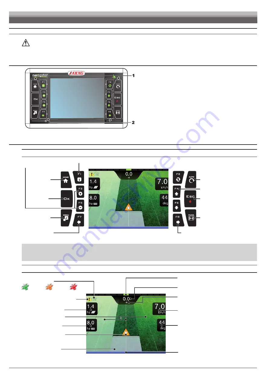
Controls on computer
Fig. 116
Legend:
1
Control and display mode keys
2
Function keys
Function keys are contextual: the function of each depends on what appears
on the display, therefore
the use of these keys will be illustrated during the
description of the corresponding procedures.
11.2
Guidance screen
USING THE KEYS
Go to “Home”
menu
Key for
confirmation
Switch to job
menu
NOT USED
ON / OFF
Aborts a function
Aborts data change
Spraying activation
Select job data
displayed on the LEFT side
Select job data
displayed on the RIGHT side
Display zoom adjustment
F3
(
+
) increases,
F5
(
-
) decreases
Displays job information / alarms (par. 13.1)
Enable / disable
the job function
view
Fig. 117
F1
÷
F8
: Contextual function keys
These keys control what is shown on the display (display zoom adjustment, etc., Fig. 117)
When the function list is displayed, they perform specific functions: the function of each key depends on what appears on the display, therefore the use of these keys
will be illustrated during the description of the corresponding procedures.
DISPLAY ITEMS
GPS signal strength:
Deviation: distance between the position of the tractor
and the track to be followed
Spray number: the reference line is 0, tracks to its
left are negative while tracks to its right are positive.
Machine position
Reference tracks
Covered area
Speed
(detected by GPS)
Enabled alarm
(Press
F1
for more details, par. 13.1)
Calculated area
Sprayed surface
Direction
Spraying boom (par. 11.3)
Led bar: graphic representation of the deviation
Each LED corresponds to the value set in par. 10.3.5
DGPS
signal
GPS
signal
Data
not valid
Fig. 118
USE


