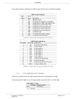
Diagnostics
Document No. D113-015
Page 49 of 77
Revision 1.9
5.
DIAGNOSTICS
5.1.
LEDS
The module provides six LEDs for diagnostics purposes as shown in the front view figure
below. A description of each LED is given in the table below.
Figure 5.1 - HART 4 module front view
LED
Description
Module
The module LED will provide information regarding the system-level operation of the
module. Thus if the LED is red then the module is not operating correctly. For example
if the module application firmware has been corrupted or there is a hardware fault the
module will have a red Module LED.
If the LED is green then the module has booted and is running correctly.
Ethernet
The Ethernet LED will light up when an Ethernet link has been detected (by plugging in
a connected Ethernet cable). The LED will flash when traffic is detected.
Channels (0-3)
Each channel LED represents the status of that specific analog channel.
The LED will be green when the loop current is within the acceptable range (3.8mA to
20.5 mA) and HART communication has been established to the field device. Otherwise
the LED will be red. The LED will flash green each time a HART response was received
from the connected field device. If there was a HART communication error (eg.
checksum failure) then the LED will flash red.
Table 5.1 - Module LED operation


