Operation
Document No. D113-015
Page 40 of 77
Revision 1.9
1
(Undefined)
2
Invalid selection
3
Passed parameter too large
4
Passed parameter too small
5
Too few data bytes received
6
Transmitter specific error
7
In write-protect mode
8-15 Command specific error
16
Access restricted
32
Device is busy
64
Command not implemented
Second Byte : Device Status
Bit
Description
0
PV out of limits
1
Variable (non-PV) out of limits
2
Analog output saturated
3
Output current fixed
4
(Undefined)
5
Cold Start
6
Configuration Changed
Table 4.6 - Status Decoding (when first byte bit 7 = 0)
If Byte 0 Bit 7 = 1 then:
First Byte : Communication Errors
Bit
Description
0
(Undefined)
1
Rx buffer overflow
2
(Undefined)
3
Checksum error
4
Framing error
5
Overrun error
6
Parity error
Second Byte : Not defined
Value
Description
0
(Always zero)
Table 4.7 - Status Decoding (when first byte bit 7 = 1)
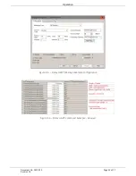
4.1.3.2.
HART COMMAND EXAMPLE
In the example below a Logix message instruction is used to Read the Unique Identifier of the
device. This makes use of the Universal Command #0. The field device is connected to channel
0, hence the Instance value set to 1.


