Operation
Document No. D113-015
Page 39 of 77
Revision 1.9
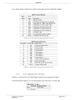
The required Request and Response HART Command structures are defined as follows:
HART Command Request
Byte
Offset
Data
Type
Description
0
INT
Request Length
2
SINT
Start Character (0x82 for Long Address)
3
SINT
Long Address 0 (0x80 + Manufacturer ID)
4
SINT
Long Address 1 (Device Type Code)
5
SINT
Long Address 2 (Device ID Byte 0)
6
SINT
Long Address 3 (Device ID Byte 1)
7
SINT
Long Address 4 (Device ID Byte 2)
8
SINT
Command Code
9
SINT
Command Data Length (in bytes)
10
SINT[]
Command Data (If required)
Table 4.4 – Relay HART Message Request Structure
HART Command Response
Byte Offset
Data Type Description
0
INT
Status (See table below)
2
INT
Packet Length
4
SINT
Start Character
5
SINT
Long Address 0
6
SINT
Long Address 1
7
SINT
Long Address 2
8
SINT
Long Address 3
9
SINT
Long Address 4
10
SINT
Command Code (Echoed)
11
SINT
Reply Data Length
12
INT
Status (Same as at byte 0 above).
14
SINT[]
Command Reply Data
Table 4.5 – Relay HART Message Response Structure
4.1.3.1.
HART COMMAND STATUS ENCODING
The Status code returned in the HART relay command can be decoded as follows:
To determine which table to use, first examine the value of the bit 7 in the first byte.
If Byte 0 Bit 7 = 0 then:
First Byte : Command Errors
Value
Description
0
No error


