Setup
Document No. D113-015
Page 20 of 77
Revision 1.9
Source
The default source of the trend data can be one of the following:
Raw Analog Current - The raw analog signal in milliamps.
Filtered Scaled Value – The analog signal in engineering units.
Digital Current – The current in milliamps reported by the field device (HART).
PV – The Primary Variable in engineering units reported via HART.
SV – The Secondary Variable in engineering units reported via HART.
TV – The Third Variable in engineering units reported via HART.
FV – The Fourth Variable in engineering units reported via HART.
Sample Rate
The period (milliseconds) between sample points. The trend data is a circular
buffer of the latest 1000 points, therefore the total trend time is 1000 * Sample
Rate.
Note: The following items apply only to the HART 4Out module.
Fail Mode
Prog / Fault Freeze
This configuration is used to determine the behaviour of the output analog signal
when the Logix controller enters a faulted or program mode.
Enabling this option freezes the output value to its last state, when a program or
fault state is detected.
Disabling this option forces the output value to the adjacent Fail Value, when a
program or fault state is detected.
This option is only valid when using the EtherNet/IP protocol.
Fail Value (Prog. / Fault)
The value, in engineering units, to be applied to the output when a program or
fault state is detected and the above Freeze option is disabled.
Comm Fail Freeze
This configuration is used to determine the behaviour of the output analog signal
when communication from the source (EtherNet/IP, DNP3 or Modbus) is lost.
Enabling this option freezes the output value to its last state, when
communication is lost.
Disabling this option forces the output value to the adjacent Fail Value when
communication is lost.
Fail Value (Comm. Fail)
The value, in engineering units, to be applied to the output when communication
from the source has been lost and the above Freeze option is disabled.
Time Out
The time, in milliseconds, since the last packet has been received from the source,
before the communication is deemed to have been lost.
Table 3.2 - Channel configuration parameters
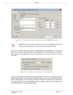
The Channel (0) configuration is shown in the figure below. This window is opened by either
double clicking on the module in the tree or right-clicking the module followed by selecting
Configuration.
Once in the configuration window select the tab corresponding to the required
channel.


