GT3000
Installation
42
IMGT30004EN
3A.6
ENCODER CONNECTION
3A.6.1
General data
"FOC" control needs an incremental encoder installed on the motor shaft (zero impulse is not necessary for standard applications).
It is possible to manage the encoder
either
line driver or push-pull
electronic circuit
. The GT3000 foresees two terminals for the feeding at 5V of
the encoder. For the connection of the encoder and the customization of the card see chapter 3A.2.4.5 and 3A.3 of the this Manual.
Encoders with whatever pulses/revolution can be used.
Maximum input frequency of the control card: FMAX = 100KHz.
The duration of the zero impulse must be included between electrical 90° and 360°.
Termination resistor for encoder line-driver: 120
Ω
The maximum speed in rpm of the encoder (motor) can be calculated using the following formula:
3A.6.2
Connection modes
Mount the eventual external feeder as close as possible to the encoder following the instructions given in chapter 3A. 4.
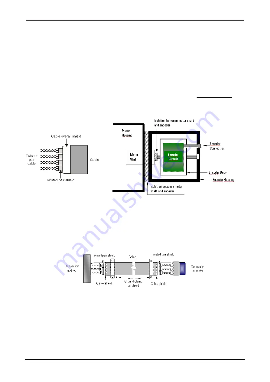
For the connection of the encoder, a cable with twisted
singularly shielded pairs shall be used.
Typical value:
single cable section: AWG24 ( 0,22mm
2
)
capacity between the cables : 50 pF/ m
capacity between cable and shied: 90 p/F m
SAP code: ELP20470101
It is compulsory:
to use an encoder with galvanic insulation between its structure and its
electronic circuits.
to use an encoder with protection against polarity inversion of power supply
and against short circuit at output.
to assembly the encoder on the motor so that to have galvanic insulation
between the motor housing/shaft and encoder.
Connect the shields of the cable to the shield bar in the converter using connections of the shortest length as possible (“pigtails”).
The ground connection of the shield is optional. It can be required to reduce the emission of radio frequency noise emitted both from the drive and
from the encoder. The connection must be performed connecting directly the shield to metallic parts (for example to the body of the encoder
avoiding pigtails) and to the ground terminal of the converter.
The cable must not be interrupted. Should it not be possible to avoid interruptions, provide for the absolute minimum length of the “pigtail” in the
connections of the shield in correspondence of each interruption. Preferably use a connection method with sturdily-built metallic terminals for the
terminations of the cable shield.
This can be obtained by blocking the single shields, or by supplying an additional total shield to be blocked by means of the terminal.
The external sheath of the cable must be removed as necessary to allow the installation of the terminal. The shield must not be broken nor open in
this point. The terminals must be installed close to the converter or to the feedback device with ground connections performed on a proper plate or
on a similar metallic surface.
Note
:
1
In the multidrive applications, if an external power supply is used, we suggest to use a power supply for every encoder.
2
If the encoder cables are longer than 60m we suggest to use encoder supplied at 24V.
3
The failure to ground connect the shield to both ends, due to noise voltage, can cause the breakage of the line driver of the
encoder and/or of the drive receiver.
olution
pulses/rev
N
60
*
F
Rev
MAX
MAX
Содержание GT3000
Страница 1: ...GT3000 Hardware Software Manual www answerdrives com ...
Страница 2: ......
Страница 4: ......
Страница 8: ...Table Of Contents GT3000 iv IMGT30017EN ...
Страница 12: ...General Safety Precautions viii IMGT30017EN ...
Страница 25: ...GT3000 Technical Data IMGT30017EN 13 Frames IV V VIN SVGT045 166 IP20 ...
Страница 26: ...Technical Data GT3000 14 IMGT30017EN Frames IV V VIN SVGT045 166 IP54 ...
Страница 27: ...GT3000 Technical Data IMGT30017EN 15 Frames IV V IP20 NEMA1 SVGT105 170K J Peso 65Kg Weight 143Lbs ...
Страница 28: ...Technical Data GT3000 16 IMGT30017EN Frames VII VIII IP00 SVGT200 521K SVGT200 470F ...
Страница 29: ...GT3000 Technical Data IMGT30017EN 17 F series Frames 2xVII 2xVIII Parallel IP00 SVGT520 940M ...
Страница 30: ...Technical Data GT3000 18 IMGT30017EN K series Frames 2xVII 2xVIII Parallel IP00 SVGT580 960K ...
Страница 32: ...20 IMGT30017EN 3A 1 3 Lifting Frame VII VIII Figure 2A 1 Methods of Unloading and Lifting GT3000 Drives ...
Страница 36: ...Installation GT3000 24 IMGT30017EN 3A 2 1 4 Frames VII VIII Installatiion ...
Страница 58: ...GT3000 Installation 46 IMGT30004EN ...
Страница 107: ...GT3000 Terminal Boards and Power Schematics IMGT30017EN 95 ...
Страница 108: ...Terminal Boards and Power Schematics GT3000 96 IMGT30017EN SVGT200 260 320K J Motor earth connection Field bus ...
Страница 109: ...GT3000 Terminal Boards and Power Schematics IMGT30017EN 97 SVGT390 521K J Field bus Motor earth connection ...
Страница 110: ...Terminal Boards and Power Schematics GT3000 98 IMGT30017EN ...


