Overview & General Specifications
10
Optima SD Instruction Manual
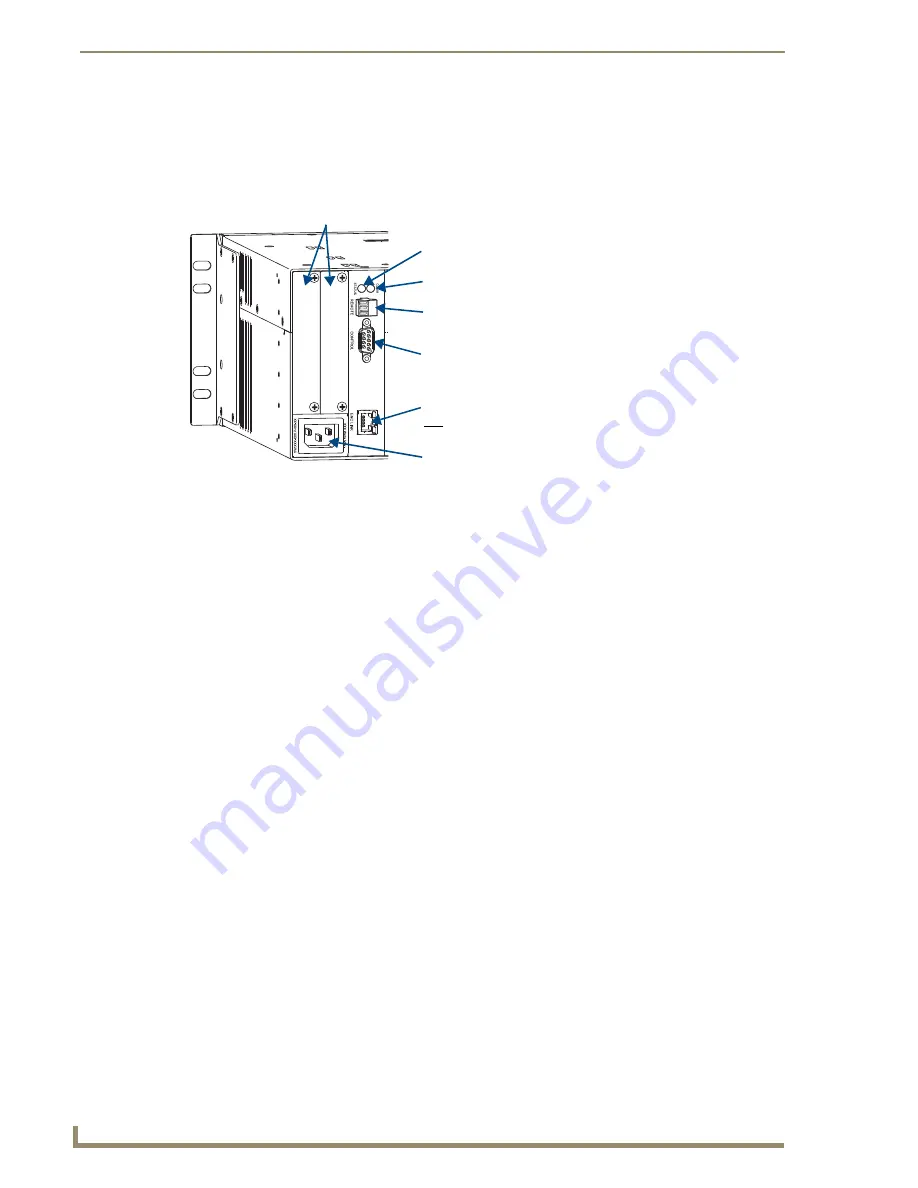
The following sections briefly introduce the hardware on the rear of an enclosure.
CPU/Control Board
The CPU is to the left of the input connectors on the rear of the enclosure (FIG. 3).
Although primarily designed as a pre-engineered, stand-alone system, the Optima SD can be linked to
other AMX AutoPatch Matrix Switchers. For information on linking between the Optima SD and other
matrix switchers, see the instruction manual for the specific product.
Note:
The Comm light on the front panel indicates Ethernet traffic on the system.
Power Receptacle & Specifications
The universal power receptacle is on the rear of the enclosure in the lower left hand corner (FIG. 3).
Maximum power specifications are on the power receptacle. The power receptacle will accept all major
international standard power sources. (Standard US power cords are provided for installations within
the US.)
The fuse is internal and is not field serviceable. If you believe the fuse needs to be replaced, contact
technical support (see page 34).
Expansion/Control Slots
Each enclosure has two expansion/control slots (FIG. 3) for expansion boards to increase functionality
and add new features to your system, such as an APWeb board for control over a LAN. If an expansion
boards is part of the original system, the board is installed at the factory.
For information on the APWeb expansion board, including connectors, cabling directions, and
establishing the APWeb server connection (plus board installation if ordered after the original system),
see page 45.
FIG. 3
CPU/Control board in Optima SD enclosure
Expansion slots
System Status indicator
– Blinks either green or red
Communication Status indicator
REMOTE port
– XNNet communication link port for linking
CONTROL port
– Serial port (RS-232) for attaching
ENC LINK port
– Ethernet (RJ-45) port used for linking enclosures.
Power receptacle
to indicate system status
to AMX AutoPatch control devices (e.g., remote control panels)
an external control device
Not to be used as a TCP/IP connection
Содержание Optima SD
Страница 11: ...Notices 6 Optima SD Instruction Manual...
Страница 19: ...Overview General Specifications 14 Optima SD Instruction Manual...
Страница 49: ...Stereo Audio Input Output Boards 44 Optima SD Instruction Manual...
Страница 81: ...Appendix C Replacing I O Boards 76 Optima SD Instruction Manual...


