


AMIFlash,
Continued
Appendix A AMIFlash Utility
92
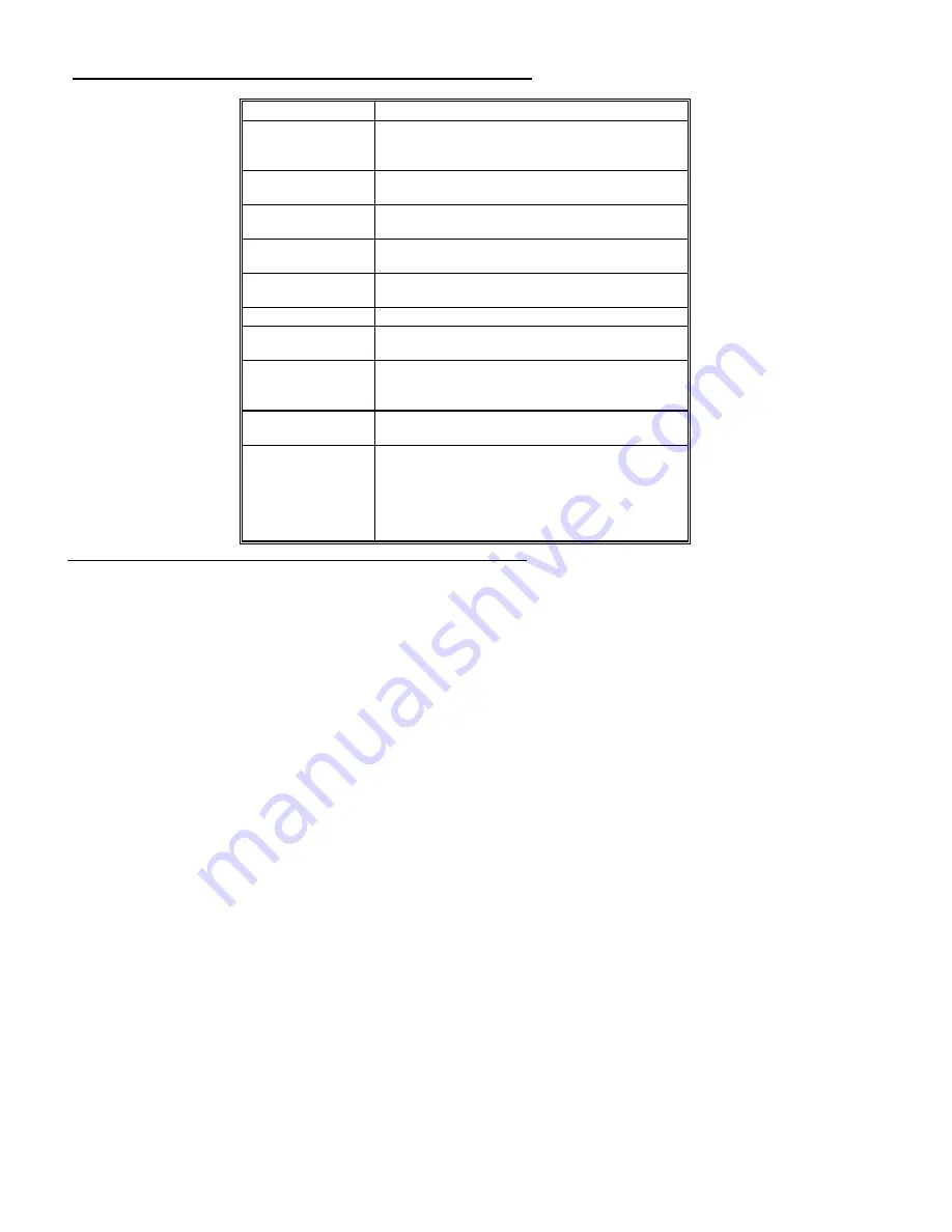
Message
Explanation
Put Off System Power
Displayed if there is an error during Flash programming.
Replace the Flash EPROM with a new programmed Flash
EPROM.
No Flash EPROM
present
Displayed if no Flash EPROM is present in the system.
Memory Allocation
Error
Displayed when scratch memory is not available.
File Creation Error
Displayed when the specified BIOS save file could not be
created.
File Does Not Exist
Displayed when the Flash EPROM program file could not
be found.
File I/O Error
Displayed during a read or write error.
Disk Full
Displayed when the disk where the existing BIOS was to
be saved has no space.
Flash EPROM
Programming Error.
Displayed if an error occurs during Flash programming.
The system is not usable unless the existing Flash EPROM
is replaced with the new Programmed Flash EPROM.
BIOS File Not Of
Proper Size
Displayed when the file size of the new program does not
match the Flash EPROM size.
Flash EPROM
Programming is going
to start
The system is not usable until Flash EPROM
programming is completed successfully. If an error occurs,
the existing Flash EPROM must be replaced by a new
programmed Flash EPROM. The system must not be
turned off during programming. The system reboots if
programming is completed successfully.
Index
8042 - Gate A20 Failure 49
Above 1 MB Memory Test 64, 65
Adapter Card
16-Bit Card Pinout 43
8-Bit Pinout 42, 43
Adapter Cards
Installing 41
Adaptor ROM BIOS 9
Advanced Setup
Floppy Drive Seek At Boot 66
Memory Test Tick Sound 65
AMIFlash 9, 84, 89
Beep Codes 87
Checkpoint codes 88
Errors 90
Aux Power Off Timeout 71
Base 64 KB Memory Failure 49
Base Memory Size 68
BIOS
Beep Codes 49
Error Reporting 47
Non-Fatal Error Messages 50
Password Support 78
POST 47
POST Memory Test 53
POST Phases 47
BIOS Setup 56
Board Layout 14
Burst Mode 6
Bus Mastering 5
C: Drive Error 50
Содержание Excalibur PCI
Страница 5: ...Excalibur PCI Pentium ISA Motherboard User s Guide 5 ...
Страница 7: ...Excalibur PCI Pentium ISA Motherboard User s Guide 7 ...
Страница 17: ...Excalibur PCI Pentium ISA Motherboard User s Guide 17 ...
Страница 19: ...Excalibur PCI Pentium ISA Motherboard User s Guide 19 ...
Страница 27: ...Excalibur PCI Pentium ISA Motherboard User s Guide 35 ...
Страница 52: ...Chapter 5 AMIBIOS POST 48 ...
Страница 60: ...Chapter 5 AMIBIOS POST 56 ...
Страница 64: ...Chapter 6 WinBIOS Setup 60 ...
Страница 82: ...Chapter 6 WinBIOS Setup 78 ...
Страница 86: ...Chapter 6 WinBIOS Setup 82 ...
Страница 88: ...Chapter 6 WinBIOS Setup 84 ...


