background image

MEGAPOWER CPU 

8200-0421-03, REV. G 

ADMINISTRATOR’S GUIDE 

8 of 82


Initializing the System 

There are two methods for initializing the 
MegaPower 3200 video-matrix CCTV system: 

  Direct connection of a PC to the CPU using either 

an RS-232 port or the Ethernet port 

  Ethernet connection through an Ethernet network 

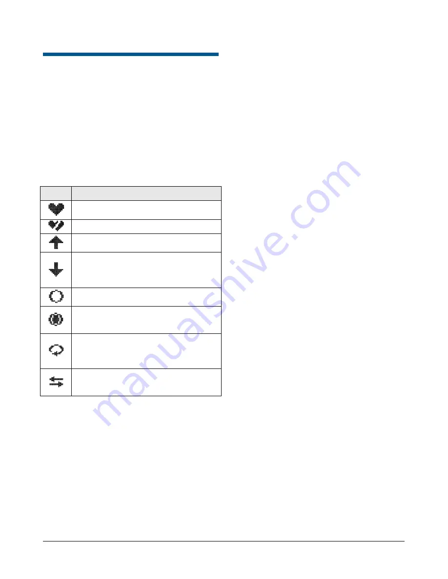
Understanding the Screen Icons 

The following icons can be seen on your CPU LCD 
screen. Some icons only appear under certain 
circumstances. 
 

Icon 

Description 


Indicates by constantly blinking on and off 
that the system is operating properly. 


Indicates the MPU is not communicating. 


Indicates the CPU that is currently active 
(selected). 


Indicates, in a dual CPU system, the CPU 
that is currently on backup (standby) status. 
This CPU still receives data while in this 
condition. 


Indicates that the system is operating 
properly. 


Indicates that an error (fault) has occurred. 
An error message is displayed with this 
icon. 


Indicates that a CPU is connected to itself 
using a single passive hot switch ribbon 
cable. No dual CPU installation is installed 
or connected. 


Indicates that both CPUs are connected 
together in a dual system using dual 
passive hot switch ribbon cables. 

Direct Connection 

Note:

 Ensure the keyboard you are using is properly 

configured for your installation. 

RS-232 Port (S

3

 Software) 

Note:

 S

software should be used only to copy an 

existing configuration from an AD1024 CPU to a 
MegaPower CPU. If you are creating a completely 
new configuration, use the EASY CPU software. 

To initialize the system, do the following: 

1.  Configure an AD1024 RS-232 port as follows: 

  Type = Terminal 

  Baud rate = 4800 bps 

  Parity = none 

  Data bits = 8 

  Stop bits = 1 

2.  Connect the PC RS-232 port to the configured 

AD1024 RS-232 port. 

3.  Open the S

3

 program. When the Transfer System 

dialog appears, click 

X

 to close it. 

4.  In the S

3

 window, click the PC Utility button at the 

bottom of the left column. A popup menu appears. 

5.  Click COMM Port Parameters in this menu, and in 

the PC Port dialog, set the parameters as follows: 

  Baud rate = 4800 bps 

  Parity = none 

  Data bits = 8 

  Stop bits = 1 

6.  Click the green check (

9

) button to accept the 

setting, and then close the dialog. 

7.  Click the PC Utility button, and then click Video 

Matrix Switch in the popup menu. 

8.  Set the Video Matrix Switch Selection field to 

AD1024

, and set Disk Drive field to 

C:

. The Video 

Matrix Switch Directory opens. 

9.  In the Directory field, type the following file name: 

C:\Program files\Sensormatic\S3\A
D1024\MPCPU

10.  Click inside any other field to create the file. This 

is the file that stores the existing AD1024 
configuration. 

11. Click the 

X

 to close the dialog, and then click the 

X

 to close the COM Port dialog. The Transfer 

System dialog opens. 

12.  Upload the configuration by clicking all the white 

check boxes in the Transfer System dialog, and 
then click the up arrow at the bottom of the 
Transfer System dialog. 

13.  Wait for the uploading process to complete, and 

then click the 

X

 to close the Transfer System 

dialog. 

14.  Disconnect the AD1024 CPU end of the PC 

RS-232 cable from the AD1024, and connect it to 
any port on the new MegaPower CPU. 

15.  Click the S

3

 PC Utility in the left column of the S

3


window, and then click COM Port Parameters in 
the popup menu. 

Содержание MegaPower ADMPCPU

Страница 1: ...8200 0421 03 G MegaPower CPU ADMPCPU Administrator s Guide...

Страница 2: ......

Страница 3: ...major components MPU Multiple Purpose Unit Port Module Figure 2 MegaPower CPU About this Guide This Administrator s Guide provides information about setting up and programming the MegaPower 3200 vide...

Страница 4: ...ons 27 Setting System Date and Time 28 Setting the Date and Time Using the Dialog Box 28 Setting the Date and Time Using the Keyboard 29 Setting Port Configurations 30 Configuring the Dome PTZ Device...

Страница 5: ...67 APPENDIX D Port Number Assignments 68 APPENDIX E Auxiliary Key Code Functions 69 F1 Special Function Keys 69 F2 Special Function Keys 69 APPENDIX F Configuring Video Loss Detection 71 APPENDIX G A...

Страница 6: ...art MPU not communicating Up arrow Selected CPU Down arrow Backup CPU Clear circle Normal operation Dark circle inside outer circle CPU fault error Circle with one arrow Single passive hot switch ribb...

Страница 7: ...include MegaPower CPU Camera monitor switching bays Fixed cameras pan tilt zoom cameras and dome cameras Video monitors Operator keyboards Video recording devices Alarm interface units Video loss dete...

Страница 8: ...local alarm contacts Camera Alarm Programming Each alarm contact can be programmed to call up a local camera Salvo Preset camera scene and auxiliary action External Control Inputs RS 232 ports allow...

Страница 9: ...h 210 for second floor cameras 301 through 310 for third floor cameras and so on Video Loss Detection When equipped with the optional Video Loss Detector module the system can detect the presence or l...

Страница 10: ...e the system do the following 1 Configure an AD1024 RS 232 port as follows Type Terminal Baud rate 4800 bps Parity none Data bits 8 Stop bits 1 2 Connect the PC RS 232 port to the configured AD1024 RS...

Страница 11: ...is 192 168 0 1 The IP address can only be changed with a keyboard connected to an RS 232 port on the CPU To initialize the system with a CPU connected directly to a PC via the Ethernet port do the fol...

Страница 12: ...is accessed ADCC1100 a Place the keyboard in Program Mode by clicking the tab in the middle of the lower part of the screen Note To display and enter Program Mode you must insert a Smartcard that has...

Страница 13: ...rd and CPU port in use 2 Use the following instructions to provide the key sequences for each supported keyboard AD2088 a Place the keyboard in Menu Mode by turning the keyswitch to MENU The CAMERA LE...

Страница 14: ...for the Standby MP CPU d Press the Ack key located in the lower right corner The System Menu screen Figure 17 appears on the LCD screen Note To exit the LCD Menu Mode press Menu Figure 17 System Menu...

Страница 15: ...following are the minimum system requirements for installing and operating the EASY CPU software application Computer PC compatible computer with 600 MHz Intel Pentium III microprocessor or greater H...

Страница 16: ...this choice is not grayed out You will be prompted to confirm that you want to end the installation Click Yes to end the installation or click No to continue the installation 4 When the following scre...

Страница 17: ...adio button and then click Next If you want to limit access to the application to just yourself click on the Only for me organization name radio button and then click Next Figure 33 Customer Informati...

Страница 18: ...3200 file EASY CPU Configurator file Configurator exe and then either double click the file name to start the application or use the Start Menu In either case EASY CPU starts and the Main Screen appea...

Страница 19: ...close the dialog box without saving your preferences 4 Close and restart EASY CPU for your change to take effect The Main Screen Figure 52 on page 23 appears in the selected language Viewing Configura...

Страница 20: ...his IP address is read only in Figure 41 The default for this field is defined in the Edit Preferences menu option MPCPU B Read from the MPCPU B IP address as defined in the System Options dialog box...

Страница 21: ...one or both of the following checkboxes Save To File When checked the configuration is saved to the path and filename shown in the associated field You can change the path filename by clicking the Br...

Страница 22: ...address is read only in Figure 46 When unchecked the configuration is not written to the indicated IP address MPCPU B When checked the configuration is written to the indicated IP address which is de...

Страница 23: ...log box appears Figure 50 Figure 50 Login Properties dialog 4 Complete the Login ID Password and Confirm fields in the Login Properties dialog box for the new user 5 In the Access Level field click on...

Страница 24: ...d the Login dialog box appears whenever you want to read a configuration file from the CPU or write a configuration file to the CPU Figure 51 Login dialog 1 In the Login dialog box enter your user nam...

Страница 25: ...Setting window display area Dropdown Menus The dropdown menus across the top of the EASY CPU main screen provide the following options File Edit Help New Open Close Save Save As Print Read Write Prop...

Страница 26: ...g boxes If you see a small triangle in the heading row for a column you can click on it to sort the rows according to the number or character sequence in that column Note Whenever you enter a value in...

Страница 27: ...loss detection not configured or no communication exists to video loss card Sync State Indicates the synchronization state of the video signal to the selected camera and is used in connection with th...

Страница 28: ...h 17 32 MegaPower CPU rear slide switch is up selecting com ports 17 32 ADDL 3 4 Low 1 16 MegaPower CPU rear slide switch is down selecting com ports 1 16 ADDL 1 2 Firmware Version Displays the MegaPo...

Страница 29: ...m Options link in the Explore menu to begin The following dialog box appears Figure 59 Figure 59 System options dialog The System Options screen provides the following options Site Number Allows you t...

Страница 30: ...ers are not available Note Although the snapshot image is simultaneously saved to all three servers it is only accessed from the currently available server Monitor Output Choose the monitor to display...

Страница 31: ...es are written to the MegaPower CPU which uses them to determine when to adjust for either DST or Standard Time This section contains the following choices Enable DST Adjustments in MPCPU Select this...

Страница 32: ...wing screen appears Figure 61 System port configuration screen To configure ports complete the following fields Port No Identifies the number of the port on the CPU to which the device is connected Ea...

Страница 33: ...When checked this checkbox causes the MPCPU to issue commands out the Direct Connect ports as configured in the lower four port group s control settings Commands are not sent through the ADDL The lowe...

Страница 34: ...schedule different alarm monitor contact tables to become active at different times and days Click on the Switching links in the Explore menu to begin Figure 63 on page 32 Figure 63 Switching links C...

Страница 35: ...c value and then select Pattern Specific Number from the dropdown list The numeric value entered will now contain a Pat prefix See the MegaPower CPU Operator s Guide 8200 0421 02 for more information...

Страница 36: ...dwell time Key points to remember when programming Tours The system allows 64 system Tours and every Tour can include up to 64 Tour entries Tours can include Salvos Presets Patterns auxiliaries and ot...

Страница 37: ...tor By doing so the user is simulating a Salvo o No Calls the next Tour entry to the monitor originally called in the Tour o Salvo Calls the first entry of a pre programmed Salvo to the monitor each o...

Страница 38: ...times The MegaPower CPU allows you to create 35 Event Timers Click on the Tours tab in the Switching Event Timer link in the Explore menu to begin The following screen appears Figure 72 Event timer T...

Страница 39: ...e at the time of the alarm You can schedule Alarm Monitor Contact Tables to become active automatically through Event Timers see page 35 Click on the Alarms links in the Explore menu to begin Figure 7...

Страница 40: ...til cleared Acknowledgement The Acknowledgement field allows you to determine how alarms will be cleared for the selected monitor Options are Instant an alarm resets immediately at its source when the...

Страница 41: ...the dialog box without saving your choices Deleting Contacts To delete contacts assigned to a monitor as defined in the Contact Arming tab do the following 1 In the upper screen click on the monitor...

Страница 42: ...Pattern number 0 3 assigned to the camera number or Salvo selected above Enter the number of a Preset or Pattern for the corresponding camera number or Salvo field as follows Figure 82 Contact Defini...

Страница 43: ...en After the alarm message is created enter the alarm message number in the Alarm Messages field of the Alarm Contact Definitions screen Email Message Text of Email message delivered to recipients des...

Страница 44: ...an identification number for the Email message Host Name Enter the IP address of the host Email server Address 1 Enter the Email address of the 1st person that you want the message to go to Address 2...

Страница 45: ...Callups View and edit Salvo call ups associated with selected cameras See Associating Salvo Callups to Cameras on page 45 Adding Camera Definitions You can create and edit camera definitions 1 To add...

Страница 46: ...ions and APPENDIX F Configuring Video Loss Detection on page 71 3 Click OK to display the new definition or Cancel to close the dialog box without displaying the definition Note Remember to save or tr...

Страница 47: ...tab screen Preset or Pattern Displays the number assigned to the preset coordinates or pattern moves that the camera will execute when that camera is called by this salvo This number is assigned in C...

Страница 48: ...four ports When a port expansion module is connected to a port port numbering adds an alpha character a b c d to each port number for example port one becomes ports 1a 1b 1c 1d port two becomes ports...

Страница 49: ...Click OK to save your monitor choices or Cancel to close the dialog box without saving your choices Adding a Range of Monitors To add monitors or a range of monitors 1 Click the Monitor Access tab in...

Страница 50: ...ve on the right side of the screen Configuring Keyboard User Keyboards and Priorities The Definitions Keyboard User Priorities screen allows the administrator to assign priority access levels to indiv...

Страница 51: ...complete the following fields Priority No Identifies a level 1 8 to this priority 1 lowest priority 8 highest priority Reset System If enabled the selected priority level can clear all programmed info...

Страница 52: ...ntrolling Access with Partitions Partitions control user access to cameras monitors keyboards and satellite sites You can partition cameras to monitors keyboards to cameras keyboards to monitors keybo...

Страница 53: ...Partitions Cameras to Monitors link in the Explore menu to begin The following screen appears Figure 110 Partitions cameras to monitors screen 2 Click Add on the right side of the upper screen The Ad...

Страница 54: ...eo trunk inputs to the selected local camera Output Identifies the monitor output from the remote site that is connected to the selected local camera input Alarm Number Specifies an alarm contact numb...

Страница 55: ...the keyboard Delete key of the PC running EASY CPU The Delete Rows dialog box appears Figure 114 Delete Rows dialog 4 Click Yes to delete the calling contact definition or No to retain the definition...

Страница 56: ...CPU Editing Keyboard Definitions Once a keyboard is defined edit the definition by highlighting the desired field and typing in the information Deleting Keyboard Definitions 1 Click the header of the...

Страница 57: ...The lower screen allows you to set up monitor access for each keyboard You can create edit and delete keyboard definitions Adding Keyboard Definitions To add new keyboard definitions 1 Click Add on t...

Страница 58: ...lower screen The keyboard number appears in the grayed out Keyboard box Figure 122 Monitor access screen You can add monitors to keyboards as well as remove them from keyboards Adding Monitors to Keyb...

Страница 59: ...he Remove button on the right side of the Monitor Access screen This removes all the monitors associated with that keyboard Associating Keyboards to Satellites The Partitions Keyboards to Satellites s...

Страница 60: ...changes before closing EASY CPU Editing Keyboard Definitions Once a keyboard is defined you can edit the definition by highlighting the information in the field and typing in new information Deleting...

Страница 61: ...screen This removes the satellite sites associated with that keyboard Associating Monitors to Cameras The Partitions Monitors to Cameras screen determines which cameras can be called to which monitor...

Страница 62: ...layed in sequence on an armed monitor and will cycle continuously until cleared Each alarm will be displayed for a pre programmed dwell time before it is succeeded by the next received alarm Disarmed...

Страница 63: ...of cameras that you want to associate with the monitor of the currently highlighted row The specified range shows all the enabled cameras by their pseudo numbers For example Figure 133 displays a rang...

Страница 64: ...en 2 Click the header of the row in the lower screen that contains the event timer definition to be deleted 3 Press the keyboard Delete key of the PC running EASY CPU The Delete Rows dialog box appear...

Страница 65: ...ntact if you have a need for service or support Our dealers are fully empowered to provide the very best in customer service and support Dealers should contact American Dynamics at 800 507 6268 or 561...

Страница 66: ...WARE PRODUCT on a remote storage device on an internal network with all of the devices and may operate such component with each device over the internal network solely in the manner set forth in any a...

Страница 67: ...Computer Software Restricted Rights at FAR 52 227 19 as applicable or similar clauses in the NASA FAR Supplement Contractor manufacturer is Sensormatic Electronics Corporation One Town Center Road Boc...

Страница 68: ...Blank Salvo None created Tour None created Event Timer None created Alarms One contact table predefined no others created Alarm Messages None created Email messages None created Definitions Cameras No...

Страница 69: ...421 03 REV G ADMINISTRATOR S GUIDE 67 of 82 APPENDIX C MegaPower CPU Front Panel LCD Menu Structure This appendix illustrates the hierarchy of screens that can be accessed on the MegaPower CPU liquid...

Страница 70: ...quest produces one or more replies to the requesting client usually to the EASY CPU Snapshot 1 UDP 4 Any 69 Used for sending JPEG images taken from a camera Uses TFTP Trivial File Transfer Protocol fo...

Страница 71: ...nly F2 Special Function Keys Function Action 1 F2 Sets on screen Time and Date display ON 2 F2 Sets on screen Time and Date display OFF 3 F2 Sets Camera Title Number Status display ON 4 F2 Sets Camera...

Страница 72: ...2 Sets video loss mode to VIDEO HIGH for camera 105 F2 Sets video loss mode automatically for called camera 106 F2 Sets DBVL mode for all cameras automatically and transfers settings to the CPUs to sy...

Страница 73: ...he Alarms Alarm Messages screen and create your alarm messages You can create up to 128 messages Refer to Alarm Messages on page 42 for more information 6 Go to the Alarms Email Messages screen and se...

Страница 74: ...irst monitor As alarms are cleared off the first monitor the stacked alarms on the second monitor are then transferred to the first monitor Dual Sequence an incoming alarm is displayed and held on the...

Страница 75: ...e 1 Associating alarm contacts with cameras Each alarm contact must be associated with a camera or a camera Salvo for automatic call up when an alarm is received Each camera or camera Salvo can be ass...

Страница 76: ...ra and one monitor and at least one monitor must be armed When an alarm is received the system creates an alarm queue entry for every monitor or group of monitors associated to the alarm contact If an...

Страница 77: ...y clears the alarm when the alarm condition returns to a non alarming state No operator acknowledgement is permitted Auto No Ack This method clears the alarm automatically 20 seconds after the alarm c...

Страница 78: ...fter the alarm closure is restored Automatic SHA A Single alarm monitor all alarms are queued and the first alarmed contact is displayed and held until cleared Alarms are removed from the queue 20 sec...

Страница 79: ...larm is displayed on the Hold DHI monitor and all subsequent alarms are queued and sequenced on the Sequence DSI monitor Alarms are removed from the Sequence monitor queue when the alarm closure is cl...

Страница 80: ...viewing patterns Monitor Block Queuing for Camera Salvos Monitor blocks are required to be able to view all cameras when Salvos are associated with alarms Block Sequence and Hold queuing can be mixed...

Страница 81: ...ble User IDs create a site number and perform other programming functions to enable or disable sharing The following local setup procedures are required for satellite remote operations Verify Satellit...

Страница 82: ..._ ___________ ________ __________ ___________ ________ __________ ___________ ________ __________ ___________ ________ __________ ___________ Video trunk Lines Local Cam input Remote Site Remote Mon o...

Страница 83: ...E EXT SYNC 50 60 Hz Site 1 Source Site Site 1 Keyboard Site 1 MegaPower CPU To other switcher bays code generators or 75 ohm termination Data Line Site 1 Monitors Site 1 Cameras Site 1 Switcher Bays V...

Страница 84: ...1 Source and Receiving Site 1 Keyboard Site 1 MegaPower CPU To other switcher bays code generators or 75 ohm termination Data Line Site 1 Monitors Site 1 Cameras Site 1 Switcher Bays Video Trunks from...

Страница 85: ......

Страница 86: ...Product specifications subject to change without notice Certain product names mentioned herein may be trade names and or registered trademarks of Tyco or other companies 8200 0421 03 G Please visit o...

Отзывы: