20 Gear Drive, Plymouth Ind. Park, Terryville, CT 06786
Tel: (860) 585-1254 Fax: (860) 584-1973 http://www.amci.com
27
CHAPTER 3
A
DDITIONAL
F
UNCTIONALITY
Brake Monitor
For press applications, the ANS1 has a
Brake Monitor
. Before the Brake Monitor can be used, it has to be
associated with one of the sixteen available inputs. The Brake Monitor reports the positions where the brake
input was released and applied as well as the starting and stopping times of the press.
Outputs can also be assigned to the Brake Monitor and signal when the starting or stopping times of the press
exceed programmed limits. These outputs will switch from active to inactive if a fault occurs.
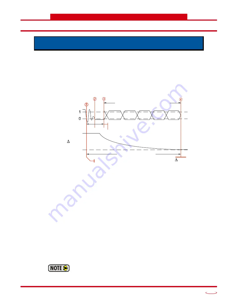
Stop Time Monitoring
Figure 3.1 Stop Time Monitor
1) The ANS1 captures the
Brake Applied Position
and starts the Stop Time Timer when the Brake Input
makes an active-to-inactive (1
0) transition. The Brake Applied Position is not immediately placed
in the input data. It is updated when the brake cycle completes.
2) Sixteen milliseconds after the initial transition, the ANS1 begins to check the state of the input every
millisecond. If the Brake Input returns to its “brake removed”, (active), state for eight milliseconds in
the next sixteen, the input transition is considered noise and the brake cycle is aborted. The next
transition on the Brake Input starts another brake cycle.
3) At the end of an additional sixteen milliseconds, (thirty-two milliseconds total), the stored states of
the input are checked. If the Brake Input is not in its “brake applied”, (inactive), state for twelve of
the last sixteen milliseconds, the input transition is considered noise and the brake cycle is aborted. If
the input is in its “brake applied” state at the end of the thirty-two milliseconds, the brake cycle
debounce steps will begin again immediately. If the input is in its “brake removed” state, the brake
cycle will start on the next transition.
Once the debounce time is exceeded, the state of the brake trigger is ignored until the brake cycle
is complete. From this point on, the Stop Time timer runs until the transducer position stops
changing. The ‘
Position’ section of the diagram shows the press coming to a stop.
4) The programmable
Complete Stop Count
parameter value is used to determine when the transducer
has come to a stop. The transducer is considered stopped when the change in position in 125
milliseconds is less than the programmed Complete Stop Count parameter value.
The Complete Stop Count parameter is always based on 4,096 counts per turn. It is
not affected by the
Counts per Cycle
and
Full Scale Count
parameters.
This chapter covers the additional functionality supplied by the ANS1. This
includes brake monitoring, die protection, and production counters
Brake
Input
Debounce Time
Brake Trigger Input = 32 mSec
Measured Stop Time
Brake Applied Position
Position
P = 0
Input State is 'Don't Care' from the end of the
Debounce Time until press has stopped.
Содержание ANS1 ANYNET-I/O
Страница 1: ...MICRO CONTROLS INC ADVANCED U s e r M anual Manual 940 0A090...
Страница 6: ...Table of Contents ADVANCED MICRO CONTROLS INC 6 Notes...
Страница 26: ...Limit Switch Functionality ADVANCED MICRO CONTROLS INC 2 26 Notes...
Страница 36: ...Additional Functionality ADVANCED MICRO CONTROLS INC 3 36 Notes...
Страница 90: ...LEADERS IN ADVANCED CONTROL PRODUCTS ADVANCED MICRO CONTROLS INC...


