


6.5
Low conductivity/high resistivity calibration
Low conductivity/high resistivity calibration difficulties often occur due to the fact that once a
sample is exposed to air the conductivity will rise rapidly due to the absorption of carbon dioxide
and other contaminants. Conductivity standard solutions of low conductivity can also be affected
by exposure to air over a period of time. The installation conditions such as pipe diameter and
material can affect the reading i.e. if the cell is calibrated outside its normal installation position
the calibration may inaccurate once the cell is installed due to the effect on conductivity paths in
the pipe. Ideally calibration should take place with the cell in its normal measuring position and
a calibration reference cell and display mounted close to this cell but not so close as to electrically
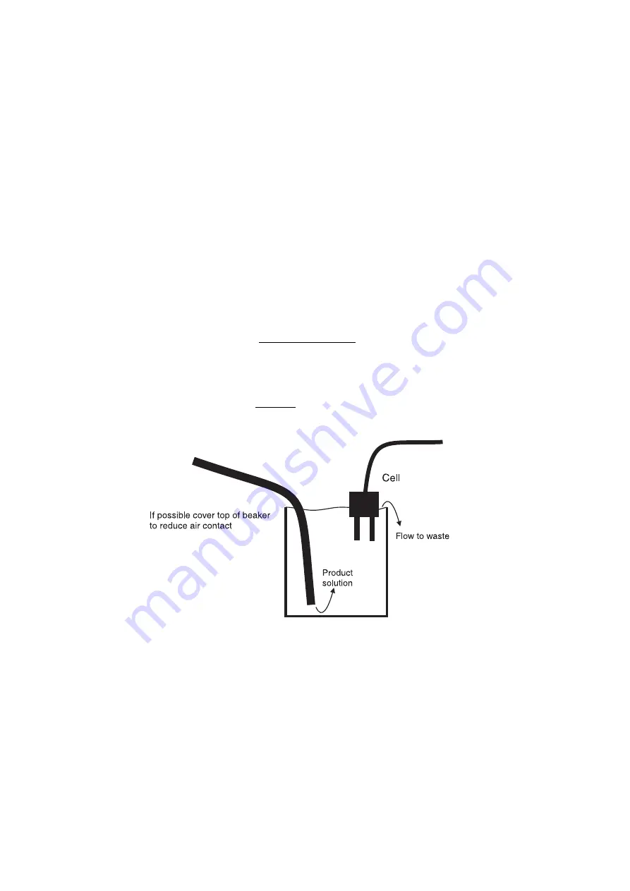
interfere. If this is not possible and the cell has to be removed for calibration then the best way
to avoid contamination is to put flowing product solution into the bottom of a container and allow
it to flow over the side. The cell is then placed in the solution as shown in the diagram below.
Note that when a resistivity display is required and calibration using high resitivity solutions is
required the instrument should be set to display conductivity rather than resistivity using the
SEt
dISP
function. The calibration should then take place as a conductivity calibration and when
calibrated the display set back to read resistivity. This procedure is necessary since the resitivity
null calibration value is too close to high resitivity solution values. The conversion formula is:
Resistivity
= (
1
Conductivity/cm
)
×
Kf actor
e.g. for 0.006 uS/cm conductivity and a K=0.1 cell
Resistivity
= (
1
0
.
006
−
6
)
×
0
.
1 = 16
.
67
M Ohms
6.6
Temperature Calibration Null
Note: the temperature sensor type should be selected, using the
"CtYPE
function, and appropri-
ate internal links set, prior to calibration. The temperature null calibration function,
"C NULL
,
allows the temperature input to be nulled or zeroed. This procedure only needs to be executed
upon initial calibration or if the temperature probe is changed. Ensure that correct temperature
probe has been selected under the
"C tYPE
function and that appropriate hardware links have
been set for the probe type (see the “Hardware Configuration” chapter). Enter the calibration
(
CAL
) mode and step through the functions until
"C NULL
is reached. Place a shorting wire
across the temperature input terminals (terminals 7, 8 and 9). Press Both
^
and
v
together, a
temperature value will be displayed then press the
F
button. The message
"CNULLEnd
should
be displayed. If any other message is seen refer to the “Error Messages” appendix.
42 of
PM4COMAN-2.2-1


