background image

14

Input Connection

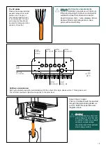
All wiring is conducted on the AC side of the inverter. The SolShare requires a three-phase, grid-connected inverter 

to be used in the PV installation. The solar input cable must come from an Inverter Supply Main Switch, ideally 

located in an accessible location from the main switchboard.
To wire the input cable into the SolShare, the following steps should be taken:
1. Measure out the 4c+e cable and cut to appropriate length.
2. Strip cable sheath back by approximately 100mm.
3.  If outdoors, select appropriate cable/conduit gland and use these to replace membrane glands. Insert 4c+e into 

SolShare via this cable/conduit glands.

4.  Cut and connect earth and neutral from input to their respective connection points. 
5.  Cut and connect phase cables as per the diagram above.

Output Connections

Please refer to your Project Single Line Diagram (SLD) on how to connect the SolShare to the main 

switchboard.
Your project SLD should have been designed in accordance to the SolShare System and SLD Design Guidelines.  

If no project SLD exists please contact project owner or system design engineer.
For ease of isolation of the SolShare, it is highly recommended that an enclosure be installed below the SolShare 

containing SolShare Maintenance Isolators (Grid). As the SolShare is a 3-phase device, it is recommended that 

these Maintenance Isolators are 3 pole with the same current rating as the Tenancy Main Switches (Inverter Supply).
The outputs from the SolShare must be wired to the SolShare Maintenance Isolators (Grid). The outputs of the 

SolShare Maintenance Isolators (Grid) must be wired to their respective Tenancy Main Switch (Inverter Supply). 
Ensure each cable is labelled with the tenancy number. This will help later on in the installation when wiring the 

current transformers to each unit.

CONNECTORS

EARTH BAR

R1 W1 B1

R2 W2 B2

R3 W3 B3

R4 W4 B4

N

N

R

W B

ONLY CONNECT THE NEUTRAL 

AND EARTH CABLES OF THE 

INPUT AND OUTPUT 1

INPUT SOLAR

OUTPUT 1

OUTPUT 2

OUTPUT 3

NEUTRAL

MINIMUM CONNECTION POINTS 

FOR CORRECT OPERATION OF 

SOLSHARE. OUTPUT R1, W1, B1 

MUST BE CONNECTED.

Содержание SolShare SOLSHARE-3P-35A-03

Страница 1: ...1 SolShare Installation Manual...

Страница 2: ...2...

Страница 3: ...eling section Updated Commissioning section V4 1 18 08 2021 Updated links Updated Commissioning Document V5 0 23 08 2021 Updated to reflect product changes associated with the removal of 4G dongle and...

Страница 4: ...Installation site selection B Installation III Electrical connection A Input output connections B Running current transformer tails C Labeling IV Commissioning A Preparing the SolShare for commissioni...

Страница 5: ...upport allumeenergy com au with any queries List of supplementary documents available online For most up to date versions of all documents including this Installation Manual scan this QR code or go to...

Страница 6: ...er name Company Electrician license number Allume SIP training certification number SolShare Connection Unit Connected eg Apt 1 Unit B Common light power No connection Single Phase Three Phase R1 W1 B...

Страница 7: ...appears at grounding points within the SolShare equipment This symbol is also used in the manual Handling and Safety Instructions SAFETY SYMBOLS INFORMATION The following safety symbols are used in th...

Страница 8: ...uipment Any violation could result in personal death or injury or damage to the device Installation is only to be conducted by a certified electrician This guide is provided to help the installer unde...

Страница 9: ...itch Inverter Supply is required on each output ideally located within the unit main switchboard between the SolShare and each unit s main switch In series with this additional SolShare Maintenance Is...

Страница 10: ...able commissioning and ongoing monitoring Do not mount the SolShare on flammable wall material 90 Mounted Vertically Do not mount the SolShare near flammable material or gases 90 Mounted Vertically En...

Страница 11: ...ecure the mounting brackets to the chosen wall for installation Allume Energy recommend using the provided fasteners to attach the brackets into a suitable stone or masonry wall If another wall materi...

Страница 12: ...inals Retain screws to replace later Important The cover should lock into place when it s pulled up properly Before beginning wiring ensure cover is locked in place by pulling down firmly To bring cov...

Страница 13: ...ram above Warning The SolShare may divert all solar energy to any one unit in a point in time As a result all input output cables should be sized for maximum solar energy output The AC cables Please c...

Страница 14: ...d have been designed in accordance to the SolShare System and SLD Design Guidelines If no project SLD exists please contact project owner or system design engineer For ease of isolation of the SolShar...

Страница 15: ...output power cables to appropriate length to reach from SolShare Maintenance Isolators Grid Label both ends of these cables with the tenancy number 3 If using SolShare Maintenance Isolators Grid Run c...

Страница 16: ...se 3 Repeat steps 1 2 for white and blue phase connector blocks 4 Plug each CT connector block into the corresponding socket of the SolShare Important Make sure colours and orientation of connectors a...

Страница 17: ...on inverter s before working on meter panel Warning Shared Solar System To isolate a single unit 1 Turn off their MAIN SWITCH INVERTER SUPPLY 2 Turn off their MAIN SWITCH NORMAL SUPPLY X X X X X X M1...

Страница 18: ...nter the SSID and password of the Wifi network that you want the SolShare to connect to 4 Once you see a confirmation page in the browser wait for the SolShare to reboot 5 Disconnect your device from...

Страница 19: ...19...

Страница 20: ...tallations in Australia Specifications are subject to changes without advanced notification For the most up to date documentation vist www allumeenergy com Allume Energy Ltd www allumeenergy com info...

Отзывы: