AT-AR220E Broadband Router Installation Guide
21
Caution
Operating Temperature: This product is designed for a maximum
ambient temperature of 40°C.
6
Caution
All Countries: Install this product in accordance with local and
National Electric Codes.
7
Powering the
Device
1. Plug the power adapter to an AC power outlet.
2. Connect the output of the power supply to the power connector on
the rear of the device.
The Power LED turns on immediately. The device then
immediately runs a series of hardware diagnostics to ensure that
the unit can operate properly.
POST (Power-
On-Self-Test)
This series of hardware diagnostics is called Power-On-Self-Test (POST).
While the POST is running, watch the front panel of the router. The Self-
Test LED stays ON during the self-test process.
If the POST succeeds without encountering any problems, the Self-Test
LED turns OFF. If the Self-Test LED stays ON, then the device has failed.
Connecting the
Router to
Computers and
Network
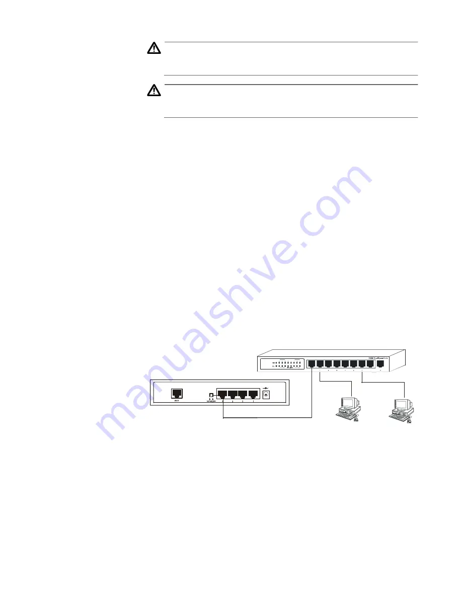
The device features a built-in 4-port 10M/100M Ethernet switch. Any of
the Ethernet ports can be connected to a computer that has an Ethernet
card or NIC (Network Interface Card). Port 4 can be used as an uplink
port to which you can connect another hub or switch, as illustrated in
Figure 1.
Figure 1 Port 4 Used as an Uplink Port
Modem
Connection
The device has one WAN port that connects to an external DSL/Cable
modem for Internet access. The following hardware items are needed
for the modem connection:
G
An external DSL/Cable modem with an Ethernet RJ-45 connector
G
An RJ-45 to RJ-45 cable for connecting the modem to the router
HUB
1 2 V dc 1 . 2A


