background image

12 


4.2.3


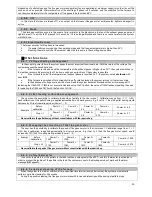
Other messages


Description 

Code 

Error on the probe during the control in the check phase 

Prob 

Notifies that the planned period of work has been achieved. The furnace or the boiler have to be 

cleaned. 

Clean 

The message appears if the system is turned off during ignition (after pre-feeding) by the external 

device: the system will stop only when it switches to an operation mode. 

Block ignition 

There is no communication between the mother board and the display (keyboard). 

Link Error 

Periodical cleaning in progress. 

Cleaning On 


4.2.4


Visualisations


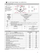
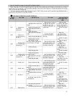
By pressing the P4 or P5 button, the visualisation menu is entered.  
Here you can see the value of the room temperature at any time, the flue gases, engine speed of flue gases, ON 

time for the auger, etc. The following indicators of the furnace work can be checked in the visualisation menu: 

Display 

Description 

Exhaust T. [ºC]   

103 

Flue gas temperature 

Room T. [ºC] 


25 

Local room temperature;  

Rem. Room T. [ºC] 

25 

Remote room temperature; only visible if the remote thermostat is active 

Air Flux 


750 

Air flow; visible only if the primary air flow meter is active 

Fan Speed [rpm] 


1250 

Exhaust gas fan speed;  

Auger [ºC] 

           1.2/450 

Auger ON time/ Auger speed;  

Cleaning [h] 


450 

Woking hours remaining before cleaning of the furnace; only visible if 

timer is activated 

Work time [h]   

2985 

Total working time of the furnace in the operative mode, modulation and 

safety 

Ignitions [h] 


106 

Number of ignition attempts 

Product Code:              494 -


0000 

Product code 


User menu 1


Press the P3 button for 1 second to enter the User menu 1. 
Use the P4 and P5 buttons to scroll through the various submenus (combustion management, heating management ...) 

and then press the P3 button to select any submenu. 

Combustion Management 
Combustion management 

Power 
In this sub-menu, it is possible to modify the system combustion power. Use the P4 and 

P5 buttons to select from 5 powers (Power 1, Power 2, Power 3, Power 4 and Power 5). When 
the desired power is selected, press P3 button to confirm. Exit the sub-menu by pressing the 
P1 button. 

Auger Calibration 
Enables the modification of the value set for the duration of the ON time of the auger. The 

values range from -7 to 7. The factory value is 0. (See item 4.6.2) 

Fan Calibration 
Enables the modification of the value set for the flue gas motor speed. The values range 

from -7 to 7. The factory value is 0. (See item 4.6.3) 

Heating Management 
Heating management 

Room Thermostat 
This  menu  allows  you  to modify  the  value  of  the  set  local  room  temperature  (the  room 

where the furnace is installed). The value of the temperature set in this menu represents a 
condition for the work of the furnace. In fact, the furnace will operate in the selected mode 
until it reaches the set temperature. When the setpoint is reached then the furnace goes into 
standby mode of work or it works with the minimum power. The furnace exits the modulation 
state  and  returns  to  normal  operation  as  soon  as  the  room  temperature  falls  below  the 
setpoint. The temperature value is adjusted by pressing P4 and P5 and then the set value is 
confirmed by pressing P3. Exit the sub-menu by pressing the P1 button. 

Remote Room Thermostat 
This menu enables the modification of the remote room thermostat value. It is visible only 

when the external thermostat is installed, whereas a heating plant that uses it is set to use an 
external thermostat. 

Remote Control 
Remote control 

This menu allows you to enable or disable the options for remote control.  

Chrono 
Chrono 

Chrono program 
Used for scheduling of operation of the furnace or for switching on and off the furnace in 

regular intervals. 

Содержание LUCA S

Страница 1: ...his user manual is an integral part of the product It has to be kept and read carefully METAL INDUSTRY VRANJE st Radni ka n 1 PELLET STOVE LUCA S LUCA S8 INSTRUCTIONS FOR ASSEMBLY USE AND MAINTENANCE...

Страница 2: ...ommissioning is performed by qualified personnel Do not use any flammable liquids for the ignition process This product should not be used by people with reduced physical sensory and mental abilities...

Страница 3: ...essary controls and checks for first ignition 9 3 2Fuel feed 9 4 Furnace management system 10 4 1Electric wiring scheme 10 4 2The control panel display use and functions 11 4 2 1 Display K100 11 4 2 2...

Страница 4: ...oblems and solutions 17 5 STOVE MAINTENANCE 18 5 1Routine maintenance 18 5 1 1 CLEANING OF THE DISPLAY AND PARTS OF THE EXTERNAL INSULATION 18 5 1 2 CLEANING OF THE CERAMIC GLASS 18 5 1 3 ROUTINE MAIN...

Страница 5: ...gher level and so as to improve the final product Seals which provide sealing of the combustion chamber must be periodically inspected to prevent undesirable combustion which may occur due to excessiv...

Страница 6: ...3 2 7 Emission of CO at 13 of oxygen 0 0136 0 0213 Efficiency 85 57 92 27 Rated electric energy W 380 Rated voltage V 230 Rated frequency Hz 50 Fuel Pellet Fuel consumption per hour kg h 1 608 0 642...

Страница 7: ...to 8 mm in the radius Wood pellets are primarily characterised by low humidity below 12 and high density 600 kg m3 as well as by its uniformity and compactness which gives this type of fuel high calor...

Страница 8: ...by the manufacturer may lead to failure of the furnace and may void the warranty When feeding the pellets be careful the pellet does not fall into another internal part of the furnace other than the s...

Страница 9: ...he product is equipped with the following safety devices Thermostat for determining the temperature of the tank This device shuts down operation of the product each time the set safety limit is exceed...

Страница 10: ...diminished 4 Have to be placed so that they are not covered in any way Adequate fresh air flow can also be provided using the opening to the next room if the room is equipped with direct ventilation a...

Страница 11: ...I Maximum height of the pipe which is connected directly to the smoke outlet in the furnace should be between 2 to 3 m If you need a horizontal segment ensure that it does not exceed 1 5 m in length a...

Страница 12: ...er resistance to atmospheric conditions as well as the proper temperature of exhaust gases themselves 2 2 2 Smoke outlet at the roof through the traditional chimney Exhaust gases from the furnace can...

Страница 13: ...ring first ignition Check whether all safety requirements have been met see section 1 8 Connect the device to the power supply only when you are sure that the supply voltage is 230 V 50 Hz When you co...

Страница 14: ...ace an advanced control system is installed which provides a safe efficient and reliable management of the operation and maximum functional use of the furnace It is characterised by Simplicity of sett...

Страница 15: ...escription System condition Code Safety error safety thermostat signals when the system is off Block Er01 Safety error pressure control signals only if the combustion fan is turned on Block Er02 Shutt...

Страница 16: ...bmenu Combustion Management Combustion management Power In this sub menu it is possible to modify the system combustion power Use the P4 and P5 buttons to select from 5 powers Power 1 Power 2 Power 3...

Страница 17: ...the P1 button Disabled Daily Weekly Week End Chrono Program Chrono program provides three types of programming Daily weekly and weekend After entering the Chrono program the following message appears...

Страница 18: ...sible to choose between programs Mon Fri Sat Sun The selected programs will be active for the days from Monday to Friday or Saturday and Sunday The programs are activated and deactivated in the same w...

Страница 19: ...ue gas motor are active Ignition Fixed Phase This phase represents a fixed time period that lasts 180 seconds and in case the requirements for the ignition of the furnace are reached before the expira...

Страница 20: ...ge Er11 indicating that the DATE TIME is not accurate Deblock using the P1 button the value of TIME flashes signalling the need for updating the TIME and DATE with the function CLOCK 4 6 2 Pellet feed...

Страница 21: ...of pellet in the burning unit is too low or too high Wait for the furnace to extinguish and then press and hold P2 button for more than 3 seconds Check the size of the pellet Check the cleanliness of...

Страница 22: ...not achieved The presence of some large obstacle or debris in the pipe for entry of primary air Wait for the furnace to extinguish and then press and hold P2 button for more than 3 seconds Check and...

Страница 23: ...tenance of the furnace ATTENTION Each cleaning activity has to be performed when the furnace is completely cold and disconnected from the power supply with the cable pulled out from the socket Number...

Страница 24: ...ties Type 2 must be carried out at about 350 400 hours or else after about 500 600 kg of fuel ATTENTION Each cleaning activity has to be performed when the furnace is completely cold and disconnected...

Страница 25: ...can be removed These parts usually must be replaced every three years depending on the type of furnace the intensity of use etc Seals must be elastic at touch and must be replaced if they become tota...

Отзывы: