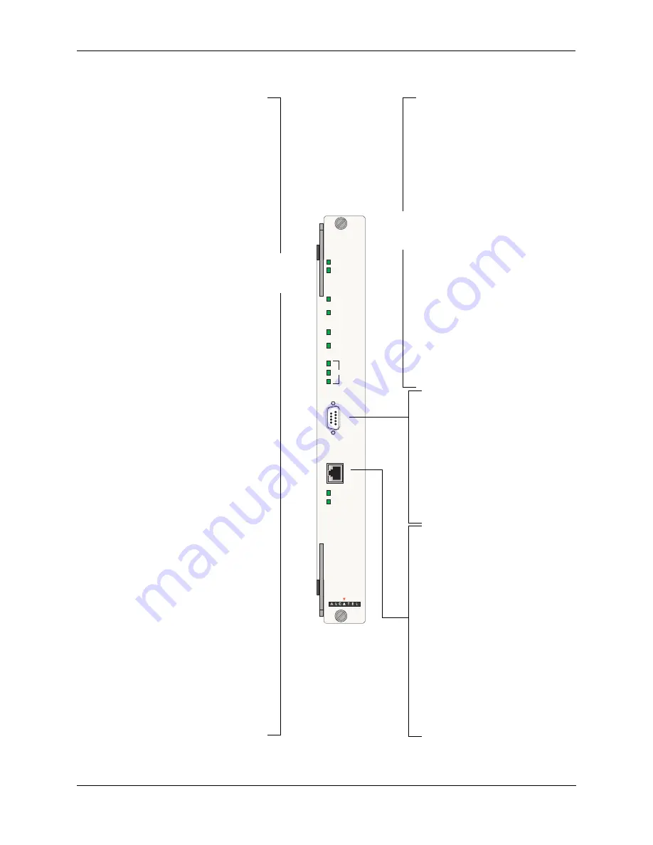
Chassis Management Module (CMM)
CMM Front Panel
OmniSwitch 8800 Hardware Users Guide
December 2004
page 3-3
CMM Front Panel
CMM Front Panel
Console/Modem Port.
The CMM’s
front panel provides one RS232 port for
console or modem connections. By
default, this female DB-9 connector
provides a DCE console connection.
However, by changing the onboard
jumper setting, the port can be changed
to a DTE modem connection.
For detailed information on changing
the jumper setting, refer to
.
Ethernet Management Port.
The
CMM’s front panel also provides one
Ethernet 10/100BaseT port (Copper
RJ45). This port provides out-of-band
network management and can be used
for Telnet sessions, switch diagnostics,
and for downloading software to the
switch.
This 10/100BaseT port supports both
10BaseT and 100BaseT with auto-
negotiation through the RJ45 connector.
Note:
In redundant CMM configura-
tions, the EMP is only operational on
the
primary
CMM. For more informa-
tion on redundant CMM configurations,
refer to
Ethernet Management Port LEDs
LINK.
Link Integrity Status. Displays
solid green when an Ethernet cable con-
nection exists at the CMM’s Ethernet
management port.
ACT.
Flashes green as data is transmit-
ted or received on the CMM’s Ethernet
management port.
Module Status LEDs
OK1.
Hardware Status. Displays solid
green when powered on and the CMM
has passed hardware diagnostic tests.
Displays solid amber when powered on
and the CMM has failed hardware diag-
nostic tests.
OK2.
Software Status. Blinks green
when the CMM is operational. Displays
solid amber when a system software
failure occurs. Blinks amber when the
software is in a transitional state (e.g.,
when software is being downloaded to
the switch).
Redundancy LEDs
PRI.
Displays solid green when the CMM is the
primary (active) management module.
SEC.
Displays solid green when the CMM is
the secondary (backup) management module.
For detailed information on CMM redundancy,
refer to
Temperature and Status LEDs
TEMP.
Displays solid green when the CMM is
operating within the allowed temperature range.
Displays solid amber if a temperature error
occurs (i.e., the CMM is operating outside the
temperature range).
If the LED indicates a temperature error, you
can use the
show temperature
command to
access more information. Refer to the
OmniSwitch CLI Reference Guide
for more
information.
STATUS.
Displays solid green when the Switch
Fabric Modules (SFMs) and power supplies are
operating normally. Displays solid amber if
there is an error in an SFM or power supply.
If the LED indicates an error, you can use the
show fabric
or
show power
command to access
more information. Refer to the
OmniSwitch CLI
Reference Guide
for more information.
FAN 1.
Displays solid green when the two fans
in the left front fan tray are running at normal
speed. Displays solid amber if a fan error occurs
(i.e., one or more fans are not running at normal
speed).
FAN 2.
Displays solid green when the two fans
in the right front fan tray are running at normal
speed. Displays solid amber if a fan error occurs
(i.e., one or more fans are not running at normal
speed).
FAN 3.
Displays solid green when the three fans
in the rear fan tray are running at normal speed.
Displays solid amber if a fan error occurs (i.e.,
one or more fans are not running at normal
speed).
If a fan LED indicates a fan error, you can use
the
show fan
command to access more informa-
tion. Refer to the
OmniSwitch CLI Reference
Guide
for more information.
Module
Status
LEDs
Module
Status
LEDs
OS8800-CMM
OK1
OK2
PRI
SEC
TEMP
FAN
STATUS
CONSOLE
/ MODEM
1
2
3
ACT
LINK
ENET


