


316
Chapter 6
Replacement Procedure
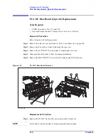
Inverter Board Replacement
Inverter Board Replacement
Tools Required
•
TORX screwdriver, T8, T10, T15, and T20
•
Flat edge screwdriver
Removal Procedure
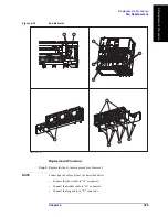
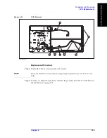
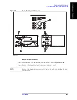
Refer to Figure 6-30 for this procedure.
Step 1.
Remove the outer cover as described in “Outer Cover Removal” on page 266.
Step 2.
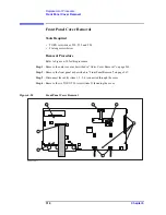
Remove the front panel as described in “Front Panel Removal” on page 267.
Step 3.
Remove the front panel cover as described in “Front Panel Cover Removal” on page 314.
Step 4.
Disconnect the three cables (item 1) connected front panel keyboard.
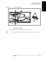
NOTE
Be careful to remove the cables (item 1), and not apply any scratches on the cables.
Step 5.
Remove the two TORX T15 screws (item 2) fastening the inverter assembly.
Step 6.
Disconnect the two cables (item 3) connected inverter assembly.
Step 7.
Remove the two TORX T8 screws (item 4) fastening the inverter to the bracket and lift it
(item 5).
Содержание E5071C
Страница 14: ...14 Contents ...
Страница 168: ...168 Chapter2 Performance Test E5071C Performance Test Record ...
Страница 212: ...212 Chapter4 Troubleshooting To configure the CPU Mother Board Assembly and BIOS ...
Страница 262: ...262 Chapter5 Replaceable Parts Power Cables and Plug Configurations ...
Страница 326: ...326 Chapter6 Replacement Procedure Probe Power and Power Switch Board Replacement ...
Страница 332: ...332 Chapter7 Post Repair Procedures Post Repair Procedures ...
Страница 360: ...360 AppendixB System Recovery Calibration of the Touch Screen ...
Страница 364: ...364 AppendixC Firmware Update Firmware Update ...
Страница 365: ...365 D Power Requirement D Power Requirement ...
Страница 367: ...Appendix D 367 Power Requirement Preparation for Power Supply D Power Requirement Figure D 1 Power cable options ...


