AGI NECO D16106 Скачать руководство пользователя страница 82

82

7713397 R2

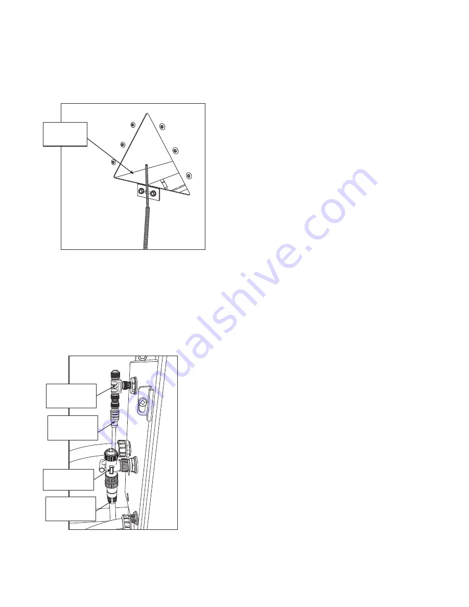
4.7.4 Install the Dual Thermocouple Probe

The dual thermocouple probe is factory mounted for each dryer section. The probe measures temperature for
high-limit temperature control in each dryer section.

Figure 95.

Dual Thermocouple Probe

Dual Thermo-

couple Probe

4.7.5 Install Burner Box Cables*

*Shipped in the dryer crate.

• The yellow and gray cables and tees are used to connect the burner boxes to each other and to the main

electrical panel.

• Directly connect the gray cable to the top burner box. (Do not install the gray tee in the top burner box.)

Figure 96.

Burner Box Connections

GREY

CABLE

YELLOW

BURNER CABLE 

TEE

GREY

COMMUNICATIONS

CABLE TEE

COMMUNICATIONS

YELLOW

BURNER

CABLE

4. ASSEMBLY

CONTINUOUS-FLOW GRAIN DRYER – COMMANDER CONTROL

Содержание NECO D16106

Страница 1: ...Number 7713397 R2 Revised June 2021 Original Instructions Continuous Flow Grain Dryer COMMANDER Control Assembly Manual This manual applies to following models D1660 D1670 D1680 D1690 D16106 D16120 D...

Страница 2: ......

Страница 3: ...the manual format All sections Removed the 12 Models Various sections Updated the table for level auger Section Roof with Level Auger on page 38 Updated the HMI wiring connections Section 4 7 10 HMI...

Страница 4: ...4 7713397 R2 CONTINUOUS FLOW GRAIN DRYER COMMANDER CONTROL...

Страница 5: ...2 1 General Design Criteria 17 2 1 1 Tier Information 17 2 1 2 Body Section Information 17 2 1 3 Standard Lengths 17 2 1 4 Total Tier Levels per Length 17 2 1 5 Dryer Model Number 18 2 1 6 Dryer Ratin...

Страница 6: ...l the Fill Switch and Low Switch 83 4 7 7 Install Moisture Temperature Sensors 86 4 7 8 Install the Discharge Chute Cables 88 4 7 9 Install Wet Bin Empty and Dry Bin Full Switches Optional 89 4 7 10 H...

Страница 7: ...uation that if not avoided may result in property damage 1 2 General Safety Read and understand all safety instructions safety decals and manuals and follow them when assembling the equipment Only exp...

Страница 8: ...rs and liquids in the vicinity of dryer Do not use the dryer where a high concentration of grain dust or flammable liquids or vapors exist such as milled grain dust Use the dryer only with the gas typ...

Страница 9: ...er before removing a guard Ensure all guards are replaced after performing maintenance 1 6 Ladder Safety Do not climb ladder if damaged wet icy greasy or slippery Remove slippery materials on platform...

Страница 10: ...iate pin and retainer Always attach safety chains Place the grain dryer in the transport position before moving on roads 1 9 Drives and Lockout Tagout Safety Inspect the power source s before using an...

Страница 11: ...and cords remain in good condition replace if necessary S E R V I C E D I S C O N N E C T ON OFF Lockout The main power disconnect switch should be in the locked position during shutdown or whenever m...

Страница 12: ...e missing or have become illegible See decal location figures that follow Replaced parts must display the same decal s as the original part Replacement safety decals are available free of charge from...

Страница 13: ...ions that the decals apply to as well as the safety precautions that must be taken to avoid serious injury death or damage Figure 1 Front Left Dryer Safety Decal Locations 035691 Outside 036725 Inside...

Страница 14: ...90B Inside 036737 079337 CSA Only Figure 4 Auger Unload Safety Decal Locations 036737 079337 CSA Only 035690 079338 CSA Only 1001985 Figure 5 Door Safety Decal Locations 079338 CSA Only One decal per...

Страница 15: ...us injury or death Keep body hair and clothing away from rotating pulleys belts chains and sprockets Do not operate with any guard removed or modified Keep guards in good working order Shut off and lo...

Страница 16: ...er d essence ou autres vapeurs ou liquides inflammables proximit de cet appareil ou de tout autre appareil Quoi faire si vous sentez une odeur de gaz N allumez aucun appareil teindre toutes les flamme...

Страница 17: ...e made up of 18 gauge material The tiers below the 18 gauge tiers will be made of heavier materials based on the required strength of that dryer configuration 2 1 2 Body Section Information An assembl...

Страница 18: ...Perimeter Service Clearance 6FT Part Serial No DRYR 1234 Burner 1 Top Voltage Phase 575VAC 3 Min Input Rate per Burner 0 5 MM BTU H Frequency 60Hz Max Input Rate per Burner 5 8 MM BTU H Control Voltag...

Страница 19: ...ollow Figure 8 Front of Dryer from Fuel Train Side MAIN CONTROL BOX CATWALK BLOWER HOUSING FUEL TRAIN PLATFORM BURNER CONTROL DRYER SECTION Each has a blower system BOX UNLOAD MOTOR Auger unload shown...

Страница 20: ...TERING ROLL DRIVE CHAINS METERING ROLL DC MOTOR UNLOAD DRIVE GUARD Shown in Open Position COOLING FLAP HANDLE LOCK Optional TRANSITION HOUSING BELT SHIELD BURNER HOUSING UNLOAD DRIVE METERING ROLLS BL...

Страница 21: ...e center plenum area Each dryer section ABOVE THE PLENUM DOOR is separated by a Divider Floor with one Divider Door for plenum access Divider Doors should always be closed during operation Optional Co...

Страница 22: ...EL AUGER ROOF WITH GRAVITY FILL Figure 12 Catwalk Positions Front of Dryer blower side Rear of Dryer Multi Blower Dryer Single Blower Dryer left center right right extended discharge Single Blower Dry...

Страница 23: ...CROP DRYING WARNING FOR OUTDOOR INSTALLATION ONLY REFER TO DRYER MANUAL FOR INSTALLATION OPERATION AND TROUBLESHOOTING INSTRUCTIONS MANUFACTURER NECO OMAHA NEBRASKA USA TEL 402 453 6912 OR 800 367 62...

Страница 24: ...c DC OUTPUT Single Parallel Vout ADJ DC LO DC ON LISTED C US U L IND CONT EQ E249179 2JF4 DRAN 120 L AC INPUT N Rdy C H1 9070T150D1 H3 H2 T150D1 110 120 115 X1 X1 X2 0025 0 15 KVA 50 60 Hz UL CSA EN60...

Страница 25: ...al window kit and heater 059242WK is available Note Do not locate the HMI screen in direct sunlight Figure 15 Example HMI Location HMI ENLOSURE 2500 AGRI GAC START STOP DRYERMASTER OFF ON FILL EMPTY D...

Страница 26: ...STOP BUTTON E STOP Schneider Electric Pushing the E STOP button will turn OFF all outputs from the PLC It does NOT shut off power into the HMI or main control panel The Power ON lamp will remain lit...

Страница 27: ...MGATE MOXA SERIAL TO ETHERNET CONVERTOR ETHERNET SWITCH 5ES 5 4 3 2 1 100 LNK 120V EIA E2A 24V GND E2 OV OV H N 12 48 VDC RESET 10 100M Ethernet Ethernet Ready P1 Part 1 Rs 232422485 MINIADAPTER MOXA...

Страница 28: ...ffic Always use hazard warning flashers on tractor towing vehicle when transporting unless prohibited by law Do not transport during times of limited visibility such as fog snow or heavy rain Take ext...

Страница 29: ...ure 19 Towable Dryer BEWARE OF POWER LINES ELECTROCUTION HAZARD FAILURE TO HEED WILL RESULT IN SERIOUS INJURY OR DEATH 040220 This dryer is not insulated Electrocution can occur without direct contact...

Страница 30: ...d 15 x 8 Wheel have six hole rims with 31 x 10 5 R15 LT tires NECO does not supply a spare tire Figure 20 Preparation for Towing OVERSIZELOAD NECO USE RED FLAGS USE REAR LIGHTS USE OVER SIZE LOAD BANN...

Страница 31: ...rain dryer parts at the assembly site and compare the packing slip to the shipment Ensure that all items have arrived and that none are damaged Take pictures of shipments prior to or just after unload...

Страница 32: ...ide These are not waterproof and will deteriorate in normal weather conditions allowing moisture to contact the parts inside If Parts Become Wet 1 If parts become submerged or wet the bundles should b...

Страница 33: ...and Propane Installation Code CSA B149 1 and the Propane Storage and Handling Code CSA B149 2 or applicable provincial regulations which should be carefully followed in all cases Authorities having j...

Страница 34: ...s Based upon the flow requirements which includes the 1 psi pressure drop use the following table to choose the line material and length that best suits the system requirements Table 5 Flow Rate MM BT...

Страница 35: ...rn off the fuel supply manual shutoff at the inlet fuel supply to the dryer Monitor the pressure of upstream and downstream pressure gauges If the pressure of any of the gauges drops to zero there cou...

Страница 36: ...sembly Hardware Key on page 36 Study this manual and look closely at the equipment overview section to become familiar with the various parts For smooth assembly the parts should organized into groups...

Страница 37: ...tem grain intake should be between 1 and 2 from the end of auger The level auger motor rotation will need to be properly conf gured by the installation electrician for proper f lling dependant upon th...

Страница 38: ...ryer Sizes Dryer Size Auger Size 8 10 Idler Shaft 16 040420 N A 24 040420 045004 Drive Shaft 16 040419 N A 24 040419 045005 Level Auger 16 7715174 N A 24 7714719 7715097 End Plates 16 7714720 N A 24 7...

Страница 39: ...ons 1 2 NUT 1 2 x 2 BOLT 6 8 1 2 x 2 1 2 BOLT 10 12 TYP ALL CONNECTIONS DRIVE SHAFT WITH KEY CONNECTION SHAFT LEVEL AUGER Note Ensure the drive end of the shaft with the keyway is on the same end as t...

Страница 40: ...red side skits to the roof 6 Using 3 8 x 1 HB FW LW and HN bolt the hanger bearing supports to the side skirts Note 12 side skirts have an extra splice placed under the bearing support to seal the gap...

Страница 41: ...97 035298 035299 HANGER BEARING HOLDER 2X HALVES HANGER BEARING HOLDER SIDE SKIRT SPLICE 1 2 x 1 1 2 HB 1 2 FW 1 2 LW 1 2 HN 1 2 HN 1 2 LW 1 2 x 1 HB Figure 28 Details of Extra Splice Plate for 12 aug...

Страница 42: ...4 x 3 4 Hex Bolt HB 1 4 Flatwasher FW 1 4 Whizlock Nut WL Cover Hardware Motor Mount Base Cover Plate Motor Mount Base Cover Plate 14 Using 5 16 x 1 HB FW LW and HN bolt the motor onto the motor mount...

Страница 43: ...lds are secure Roof with Gravity Fill Note In all instances use 1 4 x 3 4 HB FW and WL Middle panel assemblies already have the inner splice plates assembled For 16 dryers 1 The top section is already...

Страница 44: ...NOTE POSITION FILL SWITCH TOWARD THE FRONT OF DRYER 4 5 4 Catwalk and Safety Cage Assembly Note Catwalk systems are only used on models with closed roofs If the system is NOT either a Roof with Gravit...

Страница 45: ...LE 1 1 1 7712895 LADDER SUPPORT BEAM 1 1 1 7712893 LADDER SUPPORT UPRIGHTS 2 2 2 7712894 LADDER SUPPORT BRACE 2 2 2 7712568 HANDRAIL LOWER FRONT 106 2 2 2 7712567 HANDRAIL UPPER FRONT 106 2 2 2 771253...

Страница 46: ...of these toeboards TOWARD the end of dryer where ladder is 3 Using 3 8 hardware assemble 7712536 front left 106 toeboard and 7712538 front right 106 toeboards to the uprights Figure 34 Assemble front...

Страница 47: ...12986 7712536 USES HANDRAILS 7712567 7712568 USES HANDRAILS 7712567 7712568 USES HANDRAILS 7712394 7712533 USES HANDRAILS 7712567 7712568 USES HANDRAILS 7712394 7712533 7612974 16 DRYERS 24 DRYERS 32...

Страница 48: ...m access door 12 Bolt the 7612976 catwalk access cross brace between the center of the 7712569 floor splice support and either the 7612973 end toeboard for non extended catwalks or the 7712593 floor s...

Страница 49: ...bases of the support uprights Figure 39 Assemble the Ladder Support System 7712894 SUPPORT BRACE 7712893 SUPPORT UPRIGHT NOTE USE TOP HOLES TO SECURE THE SUPPORT BEAM USE BOTTOM HOLES TO SECURE THE SU...

Страница 50: ...he 7612510 handrail splice on the underside of top railings where any two top handrails butt up 26 FOR GRAVITY FILL ROOF STYLES ONLY Using 1 4 x 3 4 HB WL install 7712896 lateral braces between the in...

Страница 51: ...the 080085 ladder extensions to the bottom of the 080083 ladder connection plates For extended catwalks repeat at the opposite end if a second ladder is to be installed on the dryer opposite the stan...

Страница 52: ...oof section using one 4 ladders or two 6 and 8 ladders 080022 ladder brackets When a ladder bracket is installed at the bottom of the roof assembly a 080024 spacer must be used under the 080022 bracke...

Страница 53: ...ryers with Roofs and Catwalk System Assemble safety cage as shown in Figure 46 Use 7714611 box of hardware Figure 46 7714610 Cage for Roofs with Catwalk 7714606 7714607 7714608 7714609 CONTINUOUS FLOW...

Страница 54: ...ower section using a crane or setting it on temporary blocks etc Figure 47 Positioning the Lower Dryer Section 4 6 2 Install NECO Leg Kit Be sure to support the dryer s lower section assembly by hangi...

Страница 55: ...e 49 Using Shims USE SHIMS AS NEEDED Outer Legs and Inner Legs 1 Use 5 8 x 1 hardware 2 While the dryer lower section is hanging from a crane or setting on blocks bolt the A outer side legs only aroun...

Страница 56: ...8 WHIZLOCK NUT Figure 51 Side Leg Attachment A Table 9 Side Legs outer and inner Part Number Elevation Length inches mm inches mm 045354 48 1220 65 3 8 1661 7714575 60 1524 77 3 8 1965 Note Use 5 8 x...

Страница 57: ...the front inner legs and the A style legs for the remainder of the inner legs Use x 1 1 2 hardware Figure 52 Center Support Double B Table 10 Center Support Double Leg Part Number Elevation Length inc...

Страница 58: ...om front platform bolt the required column support leg to the I beam on top of the dryer tongue Use x 1 1 2 hardware For dryers with the bottom front platform bolt the required column support legs wit...

Страница 59: ...1965 7715832 For dryers with bottom front platform 48 1220 68 1 4 1733 7715833 60 1524 80 1 4 2038 Note Use 1 2 x 1 1 2 bolts flat and lock washers and flange nut 4 6 3 Anchor Lower Section to Pad Fou...

Страница 60: ...ing the provided hardware Figure 55 Bottom Platform Ladder 080083 3 Anchor the 040069 brackets to the concrete pad to secure the bottom of the ladder Follow the anchor manufacturer s recommendations f...

Страница 61: ...rview 1 Refer to the information contained in Section 2 Features on page 17 and Section 6 1 Dryer Tier Ladder Shipping Layouts on page 111 for specifics on layout and stacking order 2 Depending on the...

Страница 62: ...ryer section Figure 59 Stacking Sections NEXT SECTION BOTTOM SECTION PLATFORM SUPPORT COLUMNS Remove Lifting Lug Top Plates 1 Prior to stacking any dryer sections remove all 7714349 lifting lug top pl...

Страница 63: ...380 plenum end panel spacer for installation where ANY two air plenum end panels meet together 2 Position as shown in Figure 61 3 Secure when outside flange lips are bolted together Figure 61 Install...

Страница 64: ...platform mount the LOWER support column directly to the beam ALL upper sections or bottom sections with a bottom front platform use UPPER support columns and mount using 044510 support angles 3 The s...

Страница 65: ...s or use a spreader system to raise the sections 2 Use the support columns as guides and lower the section into initial position 3 Ensure that the lowering flange lips overlap properly all around Figu...

Страница 66: ...RT TUBE SUPPORT COLUMN Important Note orientation of splice plates Install Body Section Braces 1 Position and bolt a 7711498 body section brace under the overlapped outside and inside flange lips cent...

Страница 67: ...Using 1 4 hardware attach 044074 cross braces at or near every inside splice plate location Figure 69 Attach Body Section Cross Braces CROSS BRACE INSIDE SPLICE PLATES Optional Removal of Platform Bra...

Страница 68: ...platforms have the ladder system mounted at the front of dryer going up through the platform floors on the opposite side of the transition from the fuel train 2 Except for the upper most ladder secti...

Страница 69: ...milar means to properly lift the unit The main lift component should be vertical Do not use sharp angles on strapping Important Assembly of the topside filling section attached to the top most tier se...

Страница 70: ...be viewed from a main road if at all possible 2 Note that the bracket has four mounting tabs with holes that will line up with dryer tier section mounting bolts 3 Remove the necessary four sets of ti...

Страница 71: ...intake assembly to the spouts on the rear of the dryer using x 1 bolts as shown The center top cover may need to be removed for access Figure 76 Cross Auger Extension 2 For two piece cross augers con...

Страница 72: ...r sprocket to the rear chain guard as shown Verify all sprockets are aligned and adjust if needed Route the roller chain as shown slide the idler sprocket to tension the chain and then tighten the spr...

Страница 73: ...om the chain drive remove the four bolts from the top of the cover Note that the bolts run through spacers between the gearbox and the cover Take care not to lose the bolts or spacers and retain for f...

Страница 74: ...ive sprocket on the cross drag as shown Verify all sprockets are aligned and adjust if needed Use the idler sprocket to tension the chain and tighten in place Figure 83 Chain 4 Remove the sampler asse...

Страница 75: ...ount the discharge chute to the cross drag using 3 8 x 1 bolts and whiznuts Mount the diaphragm switch to the side of the discharge chute using x bolts and whiznuts Figure 85 Discharge Chute CONTINUOU...

Страница 76: ...nd nuts Depending on the lifting equipment available and the size of the enclosure the VFD enclosures can be mounted to the stands on the ground or after the stands have been raised and anchored The e...

Страница 77: ...om front platform typically only single section dryers when ordered with a blower VFD it is recommended to place the VFD enclosure next to the main control panel Use the 7716112 bracket to connect the...

Страница 78: ...rm Figure 90 Bracket 7716112 3 Anchor the stand legs to the ground following the anchor manufacturer s recommendations for installation If the VFD enclosures were not previously mounted to the stands...

Страница 79: ...ng the Control Box Height ALTERNATE MOUNTING HOLES 2 HOLE FOR MAIN POWER ENTRY 4 7 2 Final Electrical Hookup Note NECO recommends hiring an expert for proper advice accurate paperwork and safe procedu...

Страница 80: ...main control panel bottom section blower motors are already connected to the panel at the factory Holes are available on the left side of the main control panel near the bottom For dryers with blower...

Страница 81: ...ut VFD 1 Connect wires T1 T2 and T3 into the bottom of the respective starter s 2 Connect the green ground wire to the ground terminal in the control box Figure 94 Blower Motor Wiring L1 L2 L3 SINGLE...

Страница 82: ...4 7 5 Install Burner Box Cables Shipped in the dryer crate The yellow and gray cables and tees are used to connect the burner boxes to each other and to the main electrical panel Directly connect the...

Страница 83: ...ns shown in Figure 99 Figure 101 Leave any unused locations covered Connect the wiring as described in Connect Fill Switch and Low Switch on page 85 Roof with Gravity Fill System Gravity fill system i...

Страница 84: ...d 2 from the end of the dryer level auger Factory configuration per motor cable length and catwalk access has the level auger motor located at the front end of the dryer closest to the control box The...

Страница 85: ...per most dryer section burner box uses the Y split cables one cable end marked Fill and the other cable marked Low This cable will be in the dryer crate 2 Cable length supplied is sufficient to reach...

Страница 86: ...he combination moisture temperature sensing unit 059250W has a moisture sensing fin and a temperature sensing probe directly below it The sensor provides 0 to 10 VDC signals for both temperature and m...

Страница 87: ...e Note Roof with Gravity Fill AND Level Auger Fill systems locate the inlet sensor on the catwalk side of the roof See the hatch style door at the end of the catwalk for access Figure 106 Inlet Sensor...

Страница 88: ...ll capacitor box Mount the box in a convenient location ideally under the dryer or under the cross auger drag 2 Connect the yellow Sensor Motor cable from the control panel to the capacitor box 3 Drye...

Страница 89: ...off the filling equipment associated with the switch The dryer will continue to dry grain until the dryer goes into a Low Dryer alarm status 2 Place the dry bin full switch near the top of the dry hol...

Страница 90: ...ernet Cable from Main Control to HMI 1 Pull Cat 6 shielded Ethernet cable from the main control to the HMI The maximum distance should be less than 300 feet 2 Terminate each end of the Ethernet cable...

Страница 91: ...llowing diagram shows electrical and Ethernet wiring entering the HMI enclosure dashed lines Figure 114 HMI Wiring Diagram 059569 DECAL EN HMI ENCLOSURE Indoor Installation Recommended CONTINUOUS FLOW...

Страница 92: ...event thread galling utilize both pipe tape and a liquid sealant at the joints Ensure that both the tape and liquid sealant are compatible with stainless steel and the dryer fuel type Plumbing Bleeds...

Страница 93: ...Source LP connection between dryer sections CONNECT LP FUEL SOURCE NOTE MIDDLE DRYER SECTIONS WOULD HAVE A T UPPER CONNECTION THE TOP MOST DRYER SECTION WOULD HAVE AN ELBOW RISER PIPE CONTINUOUS FLOW...

Страница 94: ...bracket is not already in place it will need to be mounted to the dryer body side behind the vaporizer Position the bracket where the mounting flanges are free from obstructions and where you will hav...

Страница 95: ...the vent pipe assemblies to the fuel inlet assemblies on the dryer as shown and secure to the 041015 brackets with the provided U bolts and whiznuts Adjust the level of the brackets as needed to ensur...

Страница 96: ...2 Connect the NG fuel source to the inlet elbow of the lowest dryer section Figure 120 NG Connection Between Dryer Sections and Fuel Source Connection RISER PIPE CONNECT NG FUEL SOURCE NOTE MIDDLE DRY...

Страница 97: ...el supply manual shutoff at the inlet fuel supply to the dryer Monitor the pressure of upstream and downstream pressure gauge If the pressure of any of the gauges drops to zero there could be a leak i...

Страница 98: ...xample only Individual configuration vary Figure 121 Wet 1 Auger and Dry 1 Air System Example 2 Wet 1 and Wet 2 Augers and Dry 1 Auger The following diagram show two wet systems and one dry system to...

Страница 99: ...The dryer system s measurement units are either set to Imperial or metric Imperial units output temperature in Fahrenheight and volume in bushels Metric units output temperature in Celsius and volume...

Страница 100: ...00 1 556 11 6 3404 D24180 10 1 732 44 2 62 000 1 754 16 0 4689 D24210 12 2 020 51 3 82 500 2 334 17 4 5106 D24240 14 2 309 58 3 89 500 2 532 21 8 6391 D24260 16 2 597 66 4 110 000 3 113 23 2 6809 D243...

Страница 101: ...101 5 2 Wind Load Refer to Section 5 2 1 Wind Load Data on page 102 for dimensions for wind load calculations Figure 124 Wind Load Data Dimensions CONTINUOUS FLOW GRAIN DRYER COMMANDER CONTROL 5 SPEC...

Страница 102: ...24 7 3 31 0 9 4 D16160 16 4 9 24 7 3 35 0 10 7 D24108 24 7 3 32 9 8 21 7 6 6 D24150 24 7 3 32 9 8 25 7 7 8 D24180 24 7 3 32 9 8 29 7 9 1 D24210 24 7 3 32 9 8 33 7 10 3 D24240 24 7 3 32 9 8 37 7 11 5 D...

Страница 103: ...9296 1155 78 540 40 7 36 D24150 8 23402 10614 1443 98 124 50 8 45 D24180 10 26821 12165 1732 117 776 61 0 53 D24210 12 32187 14599 2020 137 360 71 2 62 D24240 14 36473 16543 2309 157 012 81 4 71 D2426...

Страница 104: ...ENCE ONLY RECOMMENDED FUEL SERVICE LOCATION RECOMMENDED ELECTRICAL SERVICE LOCATION STANDARD CONCRETE SURFACE PAD NON LOAD SUPPORTING SHOWN FOR REFERENCE ONLY CONTROL PANEL LOCATION STANDARD 13 0 RECO...

Страница 105: ...1 4 3 2 3 2 7 8 41 0 REFERENCE ONLY 15 0 REFERENCE ONLY RECOMMENDED FUEL SERVICE LOCATION RECOMMENDED ELECTRICAL SERVICE LOCATION STANDARD CONCRETE SURFACE PAD NON LOAD SUPPORTING SHOWN FOR REFERENCE...

Страница 106: ...MENDED FUEL SERVICE LOCATION RECOMMENDED ELECTRICAL SERVICE LOCATION STANDARD CONCRETE SURFACE PAD NON LOAD SUPPORTING SHOWN FOR REFERENCE ONLY CONTROL PANEL LOCATION STANDARD 13 0 RECOMMENDED ELECTRI...

Страница 107: ...ERVICE LOCATION RECOMMENDED ELECTRICAL SERVICE LOCATION STANDARD CONCRETE SURFACE PAD NON LOAD SUPPORTING SHOWN FOR REFERENCE ONLY CONTROL PANEL LOCATION STANDARD 13 0 RECOMMENDED ELECTRICAL SERVICE L...

Страница 108: ...FUEL SERVICE LOCATION RECOMMENDED ELECTRICAL SERVICE LOCATION STANDARD CONCRETE SURFACE PAD NON LOAD SUPPORTING SHOWN FOR REFERENCE ONLY CONTROL PANEL LOCATION STANDARD 13 0 RECOMMENDED ELECTRICAL SE...

Страница 109: ...SERVICE LOCATION RECOMMENDED ELECTRICAL SERVICE LOCATION STANDARD CONCRETE SURFACE PAD NON LOAD SUPPORTING SHOWN FOR REFERENCE ONLY CONTROL PANEL LOCATION STANDARD 13 0 3 2 3 2 2 2 1 4 2 3 3 4 5 4 1...

Страница 110: ...ERVICE LOCATION RECOMMENDED ELECTRICAL SERVICE LOCATION STANDARD CONCRETE SURFACE PAD NON LOAD SUPPORTING SHOWN FOR REFERENCE ONLY CONTROL PANEL LOCATION STANDARD 13 0 3 2 3 2 2 2 1 4 2 3 3 4 5 4 1 2...

Страница 111: ...ion Indicates ladder is 1 foot shorter for dryer with lower platform Indicates a nominal length of ladder inside plenum Actual length of ladder will be 6 shorter to fit in between floors 10 LEGEND Ind...

Страница 112: ...14S 14S 14S 14S 14S 18 18 18 18 8 8 6 8 10 8 8 10 8 6 10 10 8 4 18 18 6 6 18 18 8 10 6 18 18 6 10 6 18 18 8 6 4 10 4 10 6 1 3 24 Dryer Sections 6 12 Tiers 8 6 8 6 6 8 8 8 8 6 6 Tier D24108 8 Tier D241...

Страница 113: ...18 18 18 18 12S 12S 12S 12S 14S 14S 14S 14S 14S 14S 14 14 18 18 18 18 12S 12S 12S 12S 12S 12S 12S 12S 14S 14S 14S 14S 14S 14S 14 14 18 18 18 18 12S 12S 12S 12S 12S 12S 12S 12S 12S 12S 12S 12S 14S 14S...

Страница 114: ...14S 14S 14S 14S 12S 12S 12S 12S 18 18 18 18 14S 14S 14S 14S 14S 14S 14S 14S 12S 12S 12S 12S 12S 12S 12S 12S 18 18 18 18 14S 14S 14S 14S 14S 14S 14S 14S 12S 12S 12S 12S 12S 12S 12S 12S 12S 12S 12S 12S...

Страница 115: ...l Box Terminal Strip 24 VDC 120 VAC MODBUS COMMS E STOP WIRING AUX TRANSPORT OVERLOAD RUN CONFIRMATION SIGNALS MOISTURE SENSORS FILL SWITCH DRY BIN FULL SWITCH WET BIN EMPTY SWITCH METERING ROLL STALL...

Страница 116: ...is responsible for wiring any external transport equipment The following schematics are for reference Figure 134 Wiring Connections for External Transports TRANSPORT CONNECTIONS WET 1 DRY 2 DRY 1 WET...

Страница 117: ...7713397 R2 117 6 4 Wiring NEMA Starters IEC Starters Air Systems Figure 135 Starter and Air System Wiring Diagrams CONTINUOUS FLOW GRAIN DRYER COMMANDER CONTROL 6 APPENDIX...

Страница 118: ...R UNLOAD AUGER MOTOR NOTE Other VFDs can be used but the installer is responsible for proper connections and parameter settings for any non NECO supplied units NECO can only support VFDs supplied fact...

Страница 119: ...0 170 57 63 Lubricated 55 60 80 90 110 130 5 8 Dry 11 18 0 226 0 256 100 110 150 170 210 240 93 104 Lubricated 75 85 110 130 160 180 3 4 Dry 10 16 0 334 0 373 175 200 260 300 380 420 128 124 Lubricate...

Страница 120: ...incurring any obligation with respect to previously manufactured products Failure to follow the instructions contained in this manual as well as the existence of any of the conditions listed below wil...

Страница 121: ...7713397 R2 121 CONTINUOUS FLOW GRAIN DRYER COMMANDER CONTROL 8 LIMITED WARRANTY...

Страница 122: ...including seed fertilizer grain and feed systems with a growing platform in providing equipment and solutions for food processing facilities AGI has manufacturing facilities in Canada the United State...

Отзывы: