background image

UPS 30-300kVA User Manual

Product Specification

75

6.4.4

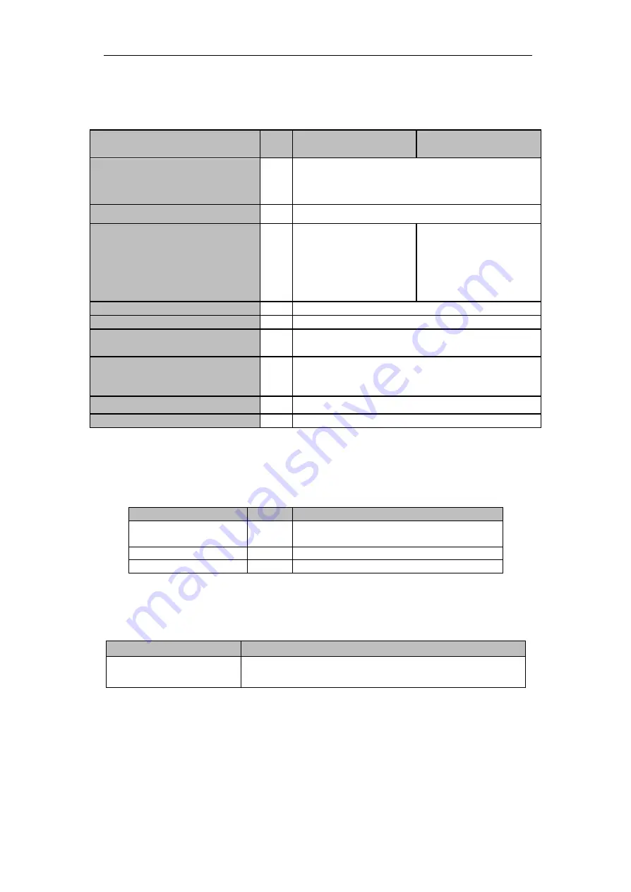
Electrical Characteristics (BypassMains Input)

Table 6-8

Bypass Mains Input

Item

Unit

60kVA-180 kVA

300 kVA

Rated AC voltage

Vac

208/220 (three-phase four-wire and sharing neutral
with the bypass)

Rated Current

A

91~758(Table3-2)

Overload

125%,

Long term

operation

125%~130%,

for 10

min

130%~150%,

for 1min

>150%,300ms

110%,

Long term

operation

110%~125%

for 5 min

125%~150%

for 1 min

>150%,1S

Current rating of neutral cable

A

1.7×In

Rated frequency

Hz

50/60

Switch time (between bypass and
inverter)

ms

Synchronized transfer: 0ms

Bypass voltage range

%

Settable,

default -20%~+15%

Up limited: +10%, +15%, +20%, +25%
Down limited: -10%,

-15%, -20%, -30%,

-40%

Bypass frequency range

Hz

Settable,

±

1Hz,

±

3Hz,

±

5Hz

Synchronized Range

Hz

Settable ±0.5Hz~±5Hz, default ±3Hz

6.5 Efficiency

Table 6-9

Efficiency

Item

Unit

30kVA~300 kVA

Normal mode(dual
conversion)

>94

ECO mode

>98

Battery mode

>93

6.6 Display and Interface

Table 6-10 Display and Interface

Display

LED + LCD +Color touch screen

Interface

Standard:

RS232, RS485, USB,

Dry Contact

Option:

SNMP,AS/400

Содержание IST6-US

Страница 1: ...rt Engineer Maintenance Engineer Note Our company is providing a full range of technical support and services Customer can contact our local office or customer service center for help The manual will...

Страница 2: ...1 UPS Configure ration 13 1 5 2 UPS Structure 13 2 Installation 16 2 1 Location 16 2 1 1 Installation Environment 16 2 1 2 Site Selection 16 2 1 3 Weight and Dimensions 16 2 2 Unloading and Unpacking...

Страница 3: ...ormal Mode into Maintenance Bypass Mode 60 4 2 5 Switching the UPS into Normal Mode from Maintenance Bypass Mode 61 4 3 Battery Manual 61 4 4 EPO 63 4 5 Installation of Parallel Operation System 64 5...

Страница 4: ...optional 71 6 Product Specification 72 6 1 Applicable Standards 72 6 2 Environmental Characteristics 72 6 3 Mechanical Characteristic 73 6 4 Electrical Characteristics 73 6 4 1 Electrical Characteris...

Страница 5: ...fety and familiar with the operation debug and maintenance of the equipment Warning Label The warning label indicates the possibility of human injury or equipment damage and advises the proper step to...

Страница 6: ...t 10 minutes for internal discharge Use a multi meter to measure the voltage on terminals and ensure the voltage is lower than 36V before operation Risk of Voltage Backfeed Beforeworking onthe circuit...

Страница 7: ...major factor in determining the battery capacity and life The nominal operating temperature of battery is 20 C Operating above this temperature will reduce the battery life Periodically change the ba...

Страница 8: ...acid At the end of battery life the battery may have internal short circuit drain of electrolytic and erosion of positive negative plates If this condition continues the battery may have temperature...

Страница 9: ...ils The UPS structure is shown inFigure 1 1 Rec fier AC DC Main Sta c Bypass Manual Bypass Inverter DC AC Charge Discharge Output Ba ery Bypass Figure 1 1UPS Conceptual Diagram 1 3 Power unit conceptu...

Страница 10: ...Indicates the energy flow direction 1 4 2 Battery Mode Upon failure of the AC mains input power the inverter ofpower unit which obtain power from the battery supply the critical AC load There is no i...

Страница 11: ...alleling of unsynchronized AC sources This interruption is programmable but typically set to be less than 3 4 of an electrical cycle e g less than 15ms 50Hz or less than 12 5ms 60Hz The action of tran...

Страница 12: ...de Rec fier AC DC Main Sta c Bypass Manual Bypass Inverter DC AC Charge Discharge Output Ba ery Bypass Figure1 7UPS conceptual diagram inECO Mode Note There is a short interruption time less than 10ms...

Страница 13: ...pass Monitoring unit 1 factory installed 90kVA 120KVA 150KVA 180KVA Manual Bypass Breaker 1 factory installed Bypass Monitoring unit 1 factory installed 210kVA 240kVA 270kVA 300kVA Circuit Breaker 4 f...

Страница 14: ...Overview 14 UPS 30 300kVA User Manual LCD Power unit Monitor and bypass unit Manual bypass b 90kVA 120kVAUPS structure c 150kVA 180kVA UPS structure...

Страница 15: ...UPS 30 300kVA User Manual Overview 15 d 210kVA 300kVA UPS structure Figure1 8UPS structure...

Страница 16: ...ensure the fresh air volume of thebattery installation environment must meet EN50272 2001 requirements If external batteries are to be used the battery circuit breakers or fuses must be mounted as clo...

Страница 17: ...UPS 30 300kVA User Manual Installation 17 500 500 800 Figure2 1 Room reserved for the cabinet Unit mm a Dimensions of 30 60KVA unit mm...

Страница 18: ...Installation 18 UPS 30 300kVA User Manual b Dimensions of 90KVA 120kVA unit mm c Dimensions of 150KVA 180kVA unit mm...

Страница 19: ...atteries and battery racks depends on the site requirements The weight for the UPS cabinet is shown in Table 2 1 Table 2 1 weight for the UPS Capacity Weight 30KVA 165 Kg 60KVA 210 Kg 90KVA 305 Kg 120...

Страница 20: ...ransport the equipment to the designated site by forklift as shown inFigure2 3 Figure2 3Transport to the designated site 3 Open the top plate of the steel edged wooden case with slotted awl and pier f...

Страница 21: ...the list of the goods If any items are not included in the list contact to our company or the local office 6 Dismantle the bolt that connects the cabinet and wooden pallet after disassembly 7 Move the...

Страница 22: ...y by the four wheels at the bottom making it convenient to adjust the position of the cabinet The other is by anchor bolts to support the cabinet permanently after adjusting the position of the cabine...

Страница 23: ...wn the anchor bolts by turning them clock wise using wrench the cabinet is then supported by the four anchor bolts 5 Ensure the four anchor bolts are in the same height and the cabinet is fixed and im...

Страница 24: ...oid electric shock hazard Ensure the positive negative neutral electrode is correctly connected from the battery unit terminals to the breaker and from the breaker to the UPS system 2 5 Cable Entry Ca...

Страница 25: ...UPS 30 300kVA User Manual Installation 25 Cable Entry a Cable Entry of 30kVA 120kVA b Cable Entry of 150kVA 180kVA...

Страница 26: ...Installation 26 UPS 30 300kVA User Manual c Top cable Entry of 210kVA and 300kVA d Bottom cable Entry of 210kVA and 300kVA Figure2 8Cable Entry...

Страница 27: ...Section 2 50 2 120 2 185 2 240 mm N 2 50 2 120 2 185 2 240 PE CableSection PE 70 2 70 2 120 2 185 mm Note The recommended cable section for power cables are only for situations described below Ambient...

Страница 28: ...minal M12 28Nm 300kVA Mains input Cables crimped OT terminal M16 96Nm Bypass Input Cables crimped OT terminal M16 96Nm Battery Input Cables crimped OT terminal M16 96Nm Output Cables crimped OT termin...

Страница 29: ...al maintenance bypass switch is opened Attach necessary warning signs to these switches to prevent unauthorized operation 2 Open the front door of the cabinet 180kVA and 300kVA open the back door remo...

Страница 30: ...otective earth terminal PE 4 Connect the AC input supply cables to the Input terminal and AC output supply cables to the Output terminal 5 Connect the Battery cables to the Battery terminal 6 Check to...

Страница 31: ...trol and Communication Cables The front panel of the bypass module provides dry contact interface J2 J11 and communication interface RS232 RS485 SNMP Intelligent card interface and USB port as it is s...

Страница 32: ...al J6 2 BCB_Status Input dry contact function issettable Default BCB Status and BCB Online Alert no battery when BCB Status is invalid J7 1 GND_DRY Ground for 24V J7 2 BCB_Online Input dry contact fun...

Страница 33: ...is in Table 2 6 J2 J3 TEMP_BAT TEMP_ENV Figure2 11J2 and J3 for temperature detecting Table 2 6Description of J2 and J3 Port Name Function J2 1 TEMP_BAT Detection of battery temperature J2 2 TEMP_COM...

Страница 34: ...t pin 2 of J5 with 24V power supply it indicates that the generator has been connected with the system The interface diagram is shown in Figure2 13 and interface description is shown in Table 2 8 J5 G...

Страница 35: ...the battery voltage is lower than set value an auxiliary dry contact signal will be activated via the isolation of a relay The interface diagram is shown in Figure2 15 and description is shown in Tabl...

Страница 36: ...ion of J10 is the output dry contact interface for utility failure warning when the utility fails the system will send a utility failure warning information and provide an auxiliary dry contact signal...

Страница 37: ...ovide serial data which can be used for commissioning and maintenance by authorized engineersor can be used for networking or integrated monitoring system in the service room SNMP Used on site install...

Страница 38: ...ontrol and operation keys and LCD touch screen 3 1 1 LEDIndicator There are 6 LEDs on the panel to indicate the operating status and fault See Figure 4 1 The description of indicators is shown in Tabl...

Страница 39: ...r supply Flashing red Overload output of UPS Off No output of UPS Status indicator Steady green Normal operation Steady red Failure There are two different types of audible alarm during UPS operation...

Страница 40: ...ber of the power module and the time of the system Warning Information Display the warning information of the cabinet Information Display Users can check the information of the cabinet in this area Th...

Страница 41: ...ltage Output Current Bypass Voltage Figure 3 3 Structure of menu tree 3 2 Main Menu The main menu includes Cabinet Power unit Setting Log Operate and Scope and it is described in details below 3 2 1 C...

Страница 42: ...s Main Output load and battery Information display Display information of each submenu The interface of each submenu is shown in Figure3 5 0 50 10 0 18 0 26 0 30 0 0 50 10 0 18 0 26 0 30 0 0 50 10 0 1...

Страница 43: ...rent Capacity The percentage compared with new battery capacity Remain T Min Remainingbatterybackup time Battery Battery Temp Ambient Environmental Temp Total Work T Total work time Total Discharge T...

Страница 44: ...er of the selected power unit Submenu The submenu includes Input Output Load INFO and S CODE Users can enter the interface of each submenu by directly touching the icon Each interface of the submenu i...

Страница 45: ...le PF Output power factor of selected module Load V Load voltage of selected module Load The percentage of the power module selected KW Pout Active Power KVA Sout Apparent Power Information BATT V Bat...

Страница 46: ...nd English selectable The setting taking action immediately after touching the language icon COMM Device Address Setting the communication address RS232 Protocol Selection SNT Protocol ModBus Protocol...

Страница 47: ...gure the rated Parameter For the factory use CONFIGURE Configure the system For the factory use Note Users have various permissions to the configuration of the Setting a for the Date Time LANGUAGE and...

Страница 48: ...Inverter feeds load 4 Load On Bypass Bypass feeds load 5 No Load No load 6 Battery Boost Charger is working in boost charging mode 7 Battery Float Charger is working in float charging mode 8 Battery...

Страница 49: ...rent The UPS alarms but has no action 21 Bypass Over Load Tout The bypass overload status continues and the overload times out 22 Byp Freq Over Track This alarm is triggered by an inverter software ro...

Страница 50: ...vice mounted in the rectifier IGBTs The UPS recovers automatically after the over temperature signal disappears If over temperature exists check 1 Whether the ambient temperature is too high 2 Whether...

Страница 51: ...ally command If UPS has been transferred to bypass manually this command enable UPS to transfer to inverter 42 Battery Volt Low Battery Voltage is Low Before the end of discharging battery voltage is...

Страница 52: ...rectly 61 Power Share Fail The difference of two or more power modules output current in system is over limitation Please adjust output voltage of power modules and restart UPS 62 Sync Pulse Fail Sync...

Страница 53: ...iency It must be confirmed that remained power modules capacity is big enough to feed load It must be conformed that working modules capacity is big enough if user add more load to UPS It s recommende...

Страница 54: ...91 Bypass CAN Fail The CAN bus between bypass module and cabinet is abnormal 92 Dust Filter Expired Dust filter need to be clear or replaced with a new one 102 Wave Trigger Waveform has been saved whi...

Страница 55: ...andESC Bypass Transfer to bypass mode or cancel this command by touching the icon or Transfer to Inverter Transfer the bypass mode to Inverter Mode by touching the icon EnableModule OFF Button Enable...

Страница 56: ...ttery Boost By touching the icon the system starts boost charging Battery Float By touching the icon the system starts float charging StopTest By touching the icon the system stops battery test or bat...

Страница 57: ...kVA only have a manual bypass breaker so need to used external circuit breakers 3 The LCD in front of the cabinet is lit up The system enters the home page as shown in Figure3 2 4 Notice the energy ba...

Страница 58: ...he battery The LED indicators are listed below in Table 4 4 Table 4 4 Normal mode Indicator Status Indicator Status Rectifier green Inverter green Battery green Load green Bypass off Status green Note...

Страница 59: ...tandard in 400kVA and 500kVA 4 2 Procedure for Switching between Operation Modes 4 2 1 Switchingthe UPS into Battery Mode from Normal Mode The UPS transfers to Battery model immediately after the util...

Страница 60: ...transfer to Normal mode by manual 4 2 4 Switchingthe UPS from Normal Mode into Maintenance BypassMode These following procedures can transfer the load from the UPS inverter output to the maintenance...

Страница 61: ...to inverter output 1 One by one to turn on the output breaker Q4 input breaker Q1 bypass input breaker Q2 and then the system starts initializing 2 After 30S the static bypass turns on the bypass ind...

Страница 62: ...the CONFIGURE page of the menu Setting tick the Battery Auto Discharge and confirm This needs to be done by factory b Setting period for battery auto discharge Enter the BATTERY page of the Setting Se...

Страница 63: ...verter and stop powering the load immediately including the inverter and bypass and the battery stops charging or discharging If the input utility is present the UPS control circuit will remain active...

Страница 64: ...ure4 6 UPS1 UPS2 Load Connect ed Output Power Suppl y Power Suppl y Figure 4 6 Parallel diagram The parallel interfaces of 60kVA 200kVAarelocatedin the front panel of the cabinet and the 400kVA 500kVA...

Страница 65: ...for the parallel operation must be connected with all single devices to form a closed loop as is shown in Figure4 8 Figure 4 8 Parallel connection For more details of parallel operation please refer t...

Страница 66: ...2 Power off the power unit a Enable LCD panel Menu Operate Enable Module OFF icon b Press the OFF button on the power unit panel for 3 seconds the power unit quits from the system 3 Remove the mounti...

Страница 67: ...rn off the manual bypass breaker 11 After 30S the rectifier starts the rectifier indicator LED goes green and then inverter starts 12 After 60S the system transfers to Normal mode 5 3 3 Maintaining mo...

Страница 68: ...cell of 2V For the setting as is shown in Figure5 1 if the battery is 40 it means that there are 40 blocks of batteries and both the positive and negative are 20 blocks of batteries In the case of ce...

Страница 69: ...4 4 Float and BoostCharge Setting In boost charging the system charges the batteries with constant current After the period the system will enter the float charging For the Lead Acid battery the defa...

Страница 70: ...tage goes higher 5 4 8 BoostCharge Time Limit This is for setting the Boost Charge time The system transfers to float charge when the boost Charge time has passed The setting range can be 1 48h 5 4 9...

Страница 71: ...of the battery and environment and give warning of overheat The set range is 25 70 The temperature sensor should be placed through the Dry Contact 5 5 Replacing Dust Filter optional There are 3 4 dust...

Страница 72: ...2 AS62040 2 C3 Method of specifying the performance and test requirements of UPS EN50091 3 IEC62040 3 AS62040 3 VFI SS 111 Note The above mentioned product standards incorporate relevant compliance c...

Страница 73: ...Unit 30kVA power unit Mechanical Dimension W D H mm 510 700 178 Weight kg 45 6 4 Electrical Characteristics 6 4 1 Electrical Characteristics Input Rectifier Table 6 5 Rectifier AC input Mains Item Un...

Страница 74: ...scharge current EOD voltage changes linearly within the set range according to discharge current Battery Charge V cell 2 4V cell selectable from 2 3V cell 2 45V cell Constant current and constant volt...

Страница 75: ...n 150 1S Current rating of neutral cable A 1 7 In Rated frequency Hz 50 60 Switch time between bypass and inverter ms Synchronized transfer 0ms Bypass voltage range Settable default 20 15 Up limited 1...

Отзывы: